

Cars
The rough idea for this project is to build 4 cars (small groups working on each).
Each car follows the same rough design: front-wheel drive with 2 geared DC Motors, a third caster wheel at the back for stabilisation and enough room to mount at least an Arduino UNO
Hardware
As with the hexapod, we decided to take advantage of the school laser cutter to manufacture the frames. Two of the designs were just one piece - a basic frame that the wheels can be glued/screwed to the bottom of and enough space on the top to mount the electronics. The other two designs built upon this idea - adding sides and tops which will be glued together to conceal the electronics and make the final outcome more robust.
Here is a screenshot of the final designs which took about 2 meetings to complete:
*note to self, take a screenshot*
We then laser cut them:
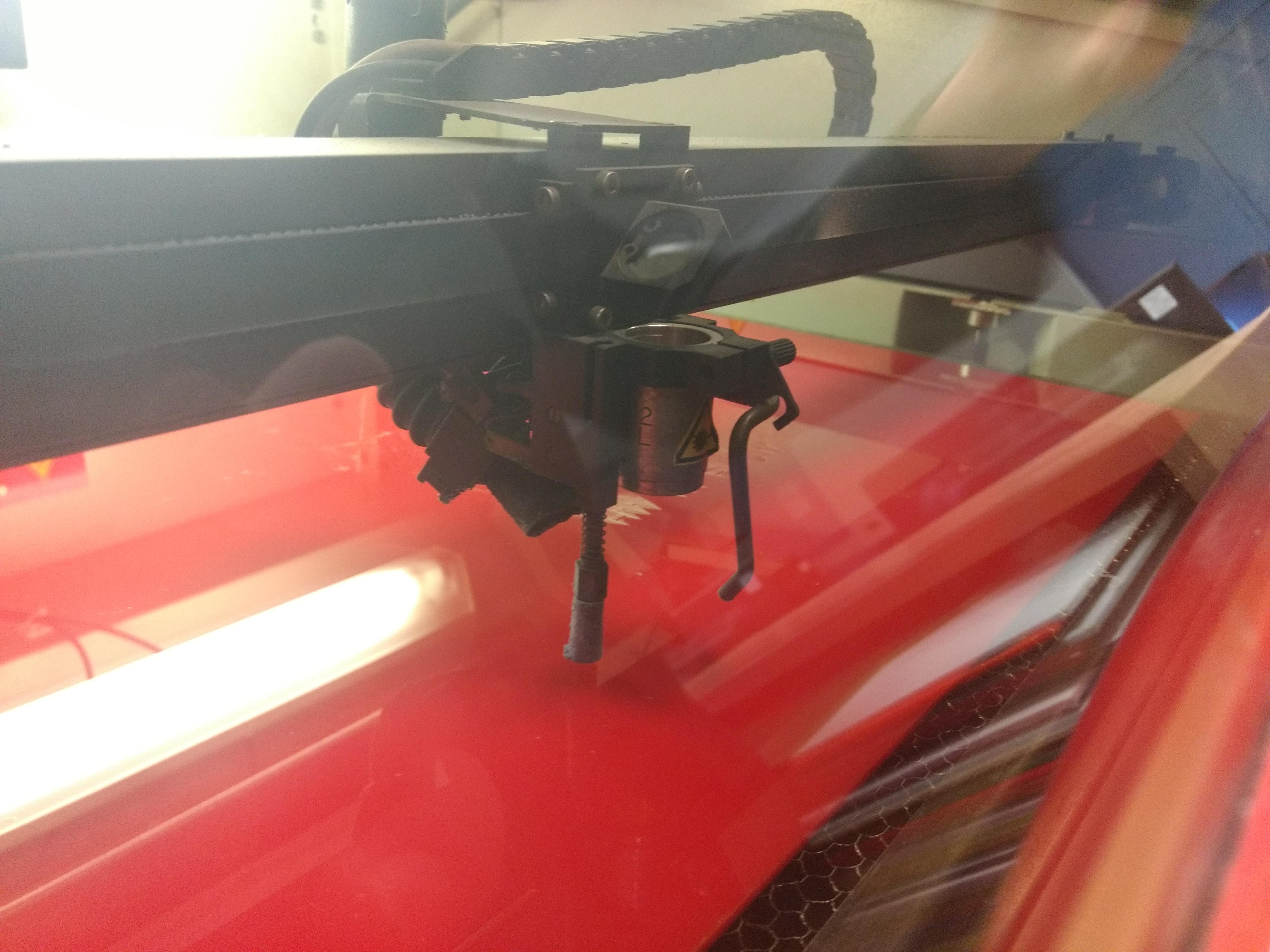
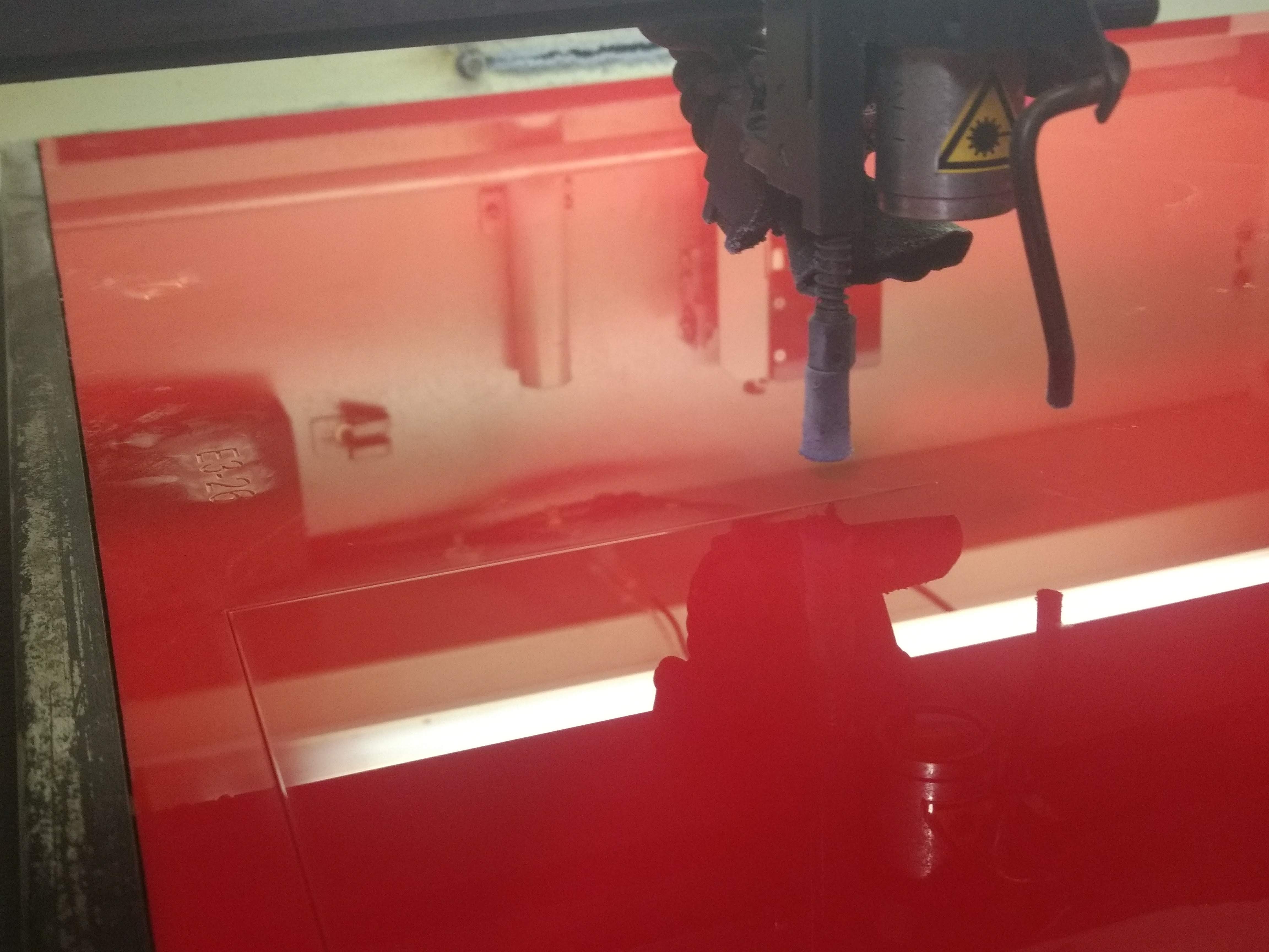
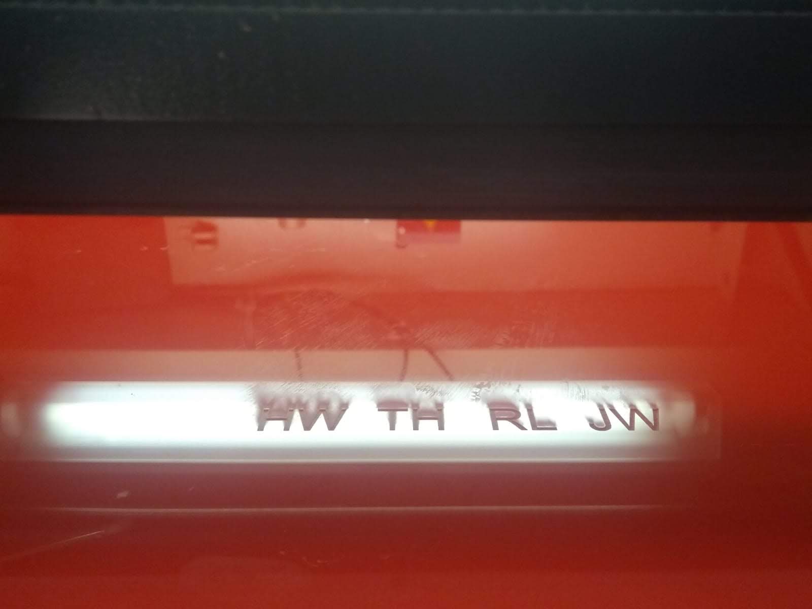
WARNING: The next video is in portrait which is horrible, however I thought the coolness of the cutting made up for it.
And that was the frames finnished!
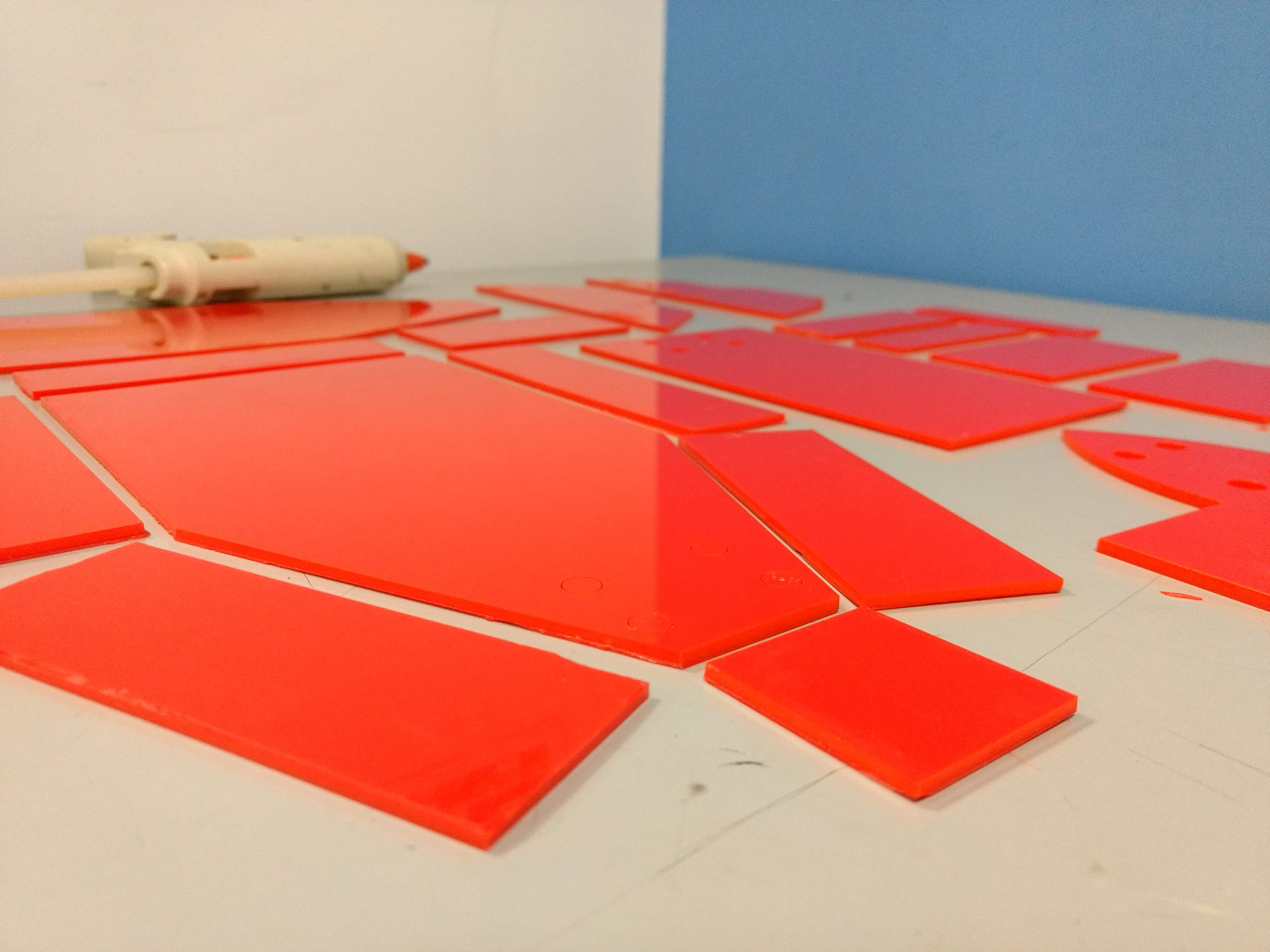
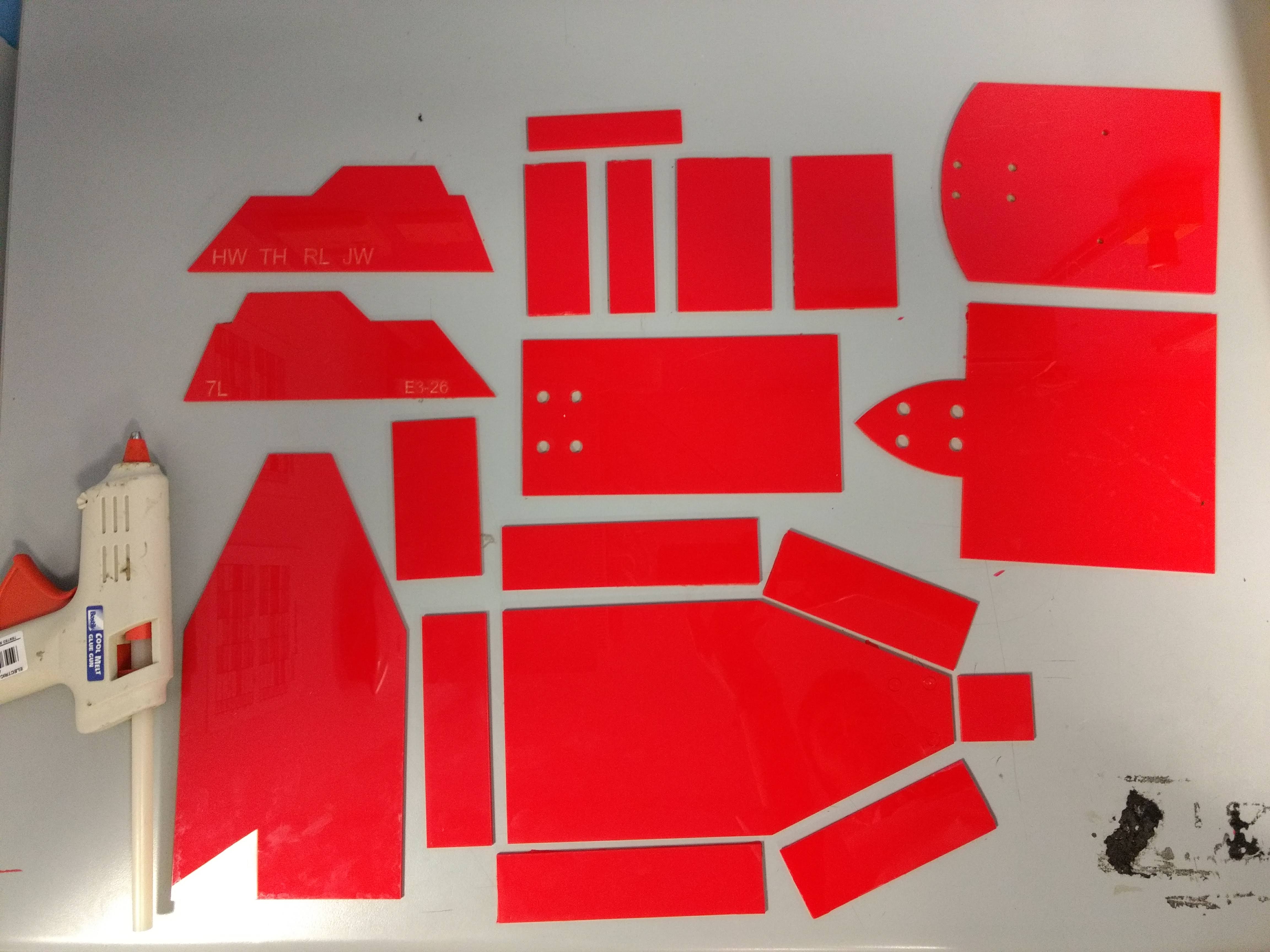
(Sorry for the non-orthogonal arrangement, it was a rushed picture!)
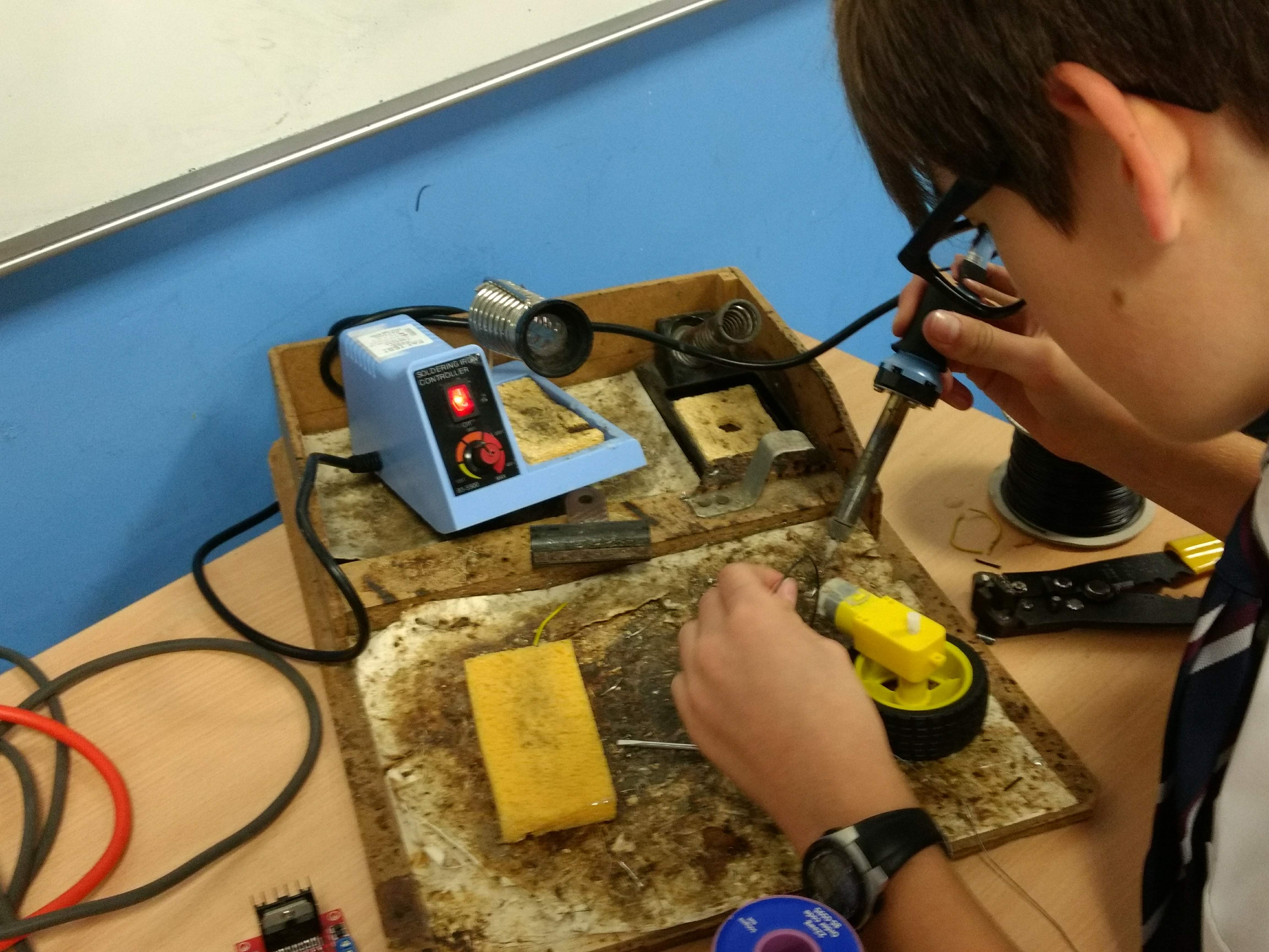
Then, as some glued their "roofs" together, the others got to soldering the motors:
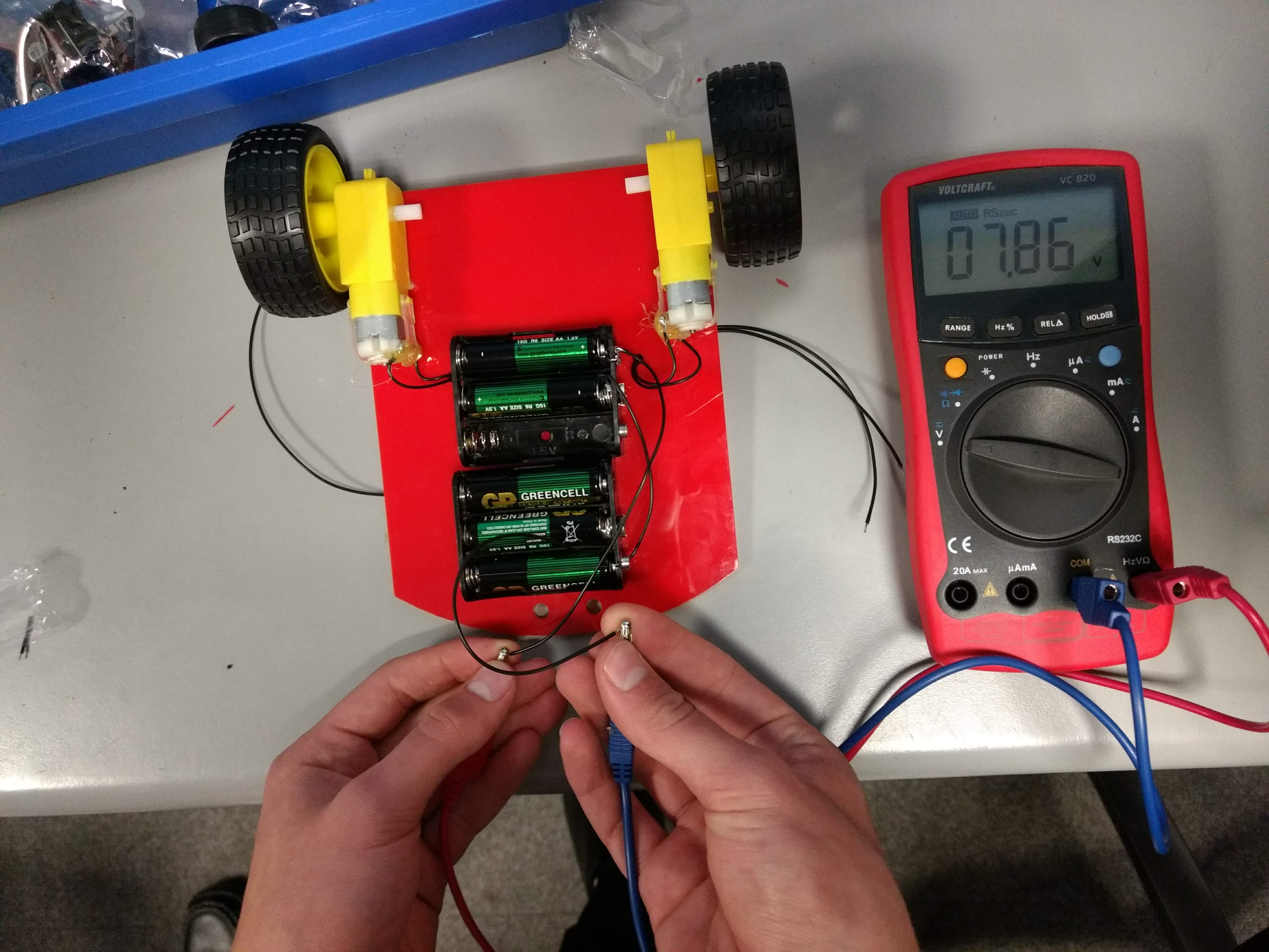
As for powering the cars, we had to consider the motors' power source and the Aduino's. The motors take roughly 5V-9V; the Arduino needs either a regulated 5V power source, or a 7V-22V unregulated source. However, if were to make the two parts share the same power source, the backlash from the DC Motors would wreck the power supply for the Arduino. Thus we decided on using a seperate 9V battery for the Arduino and 5 AA batteries for the motors - giving ~7.5 (we later upgraded to 6 for the extra speed).
Here is how we mounted the batteries to one of the cars:
And that pretty much concludes the cars. It is clear in the next section how we ended up mounting the rest of the components (switch, 9V battery, motor driver, Aduino etc.).
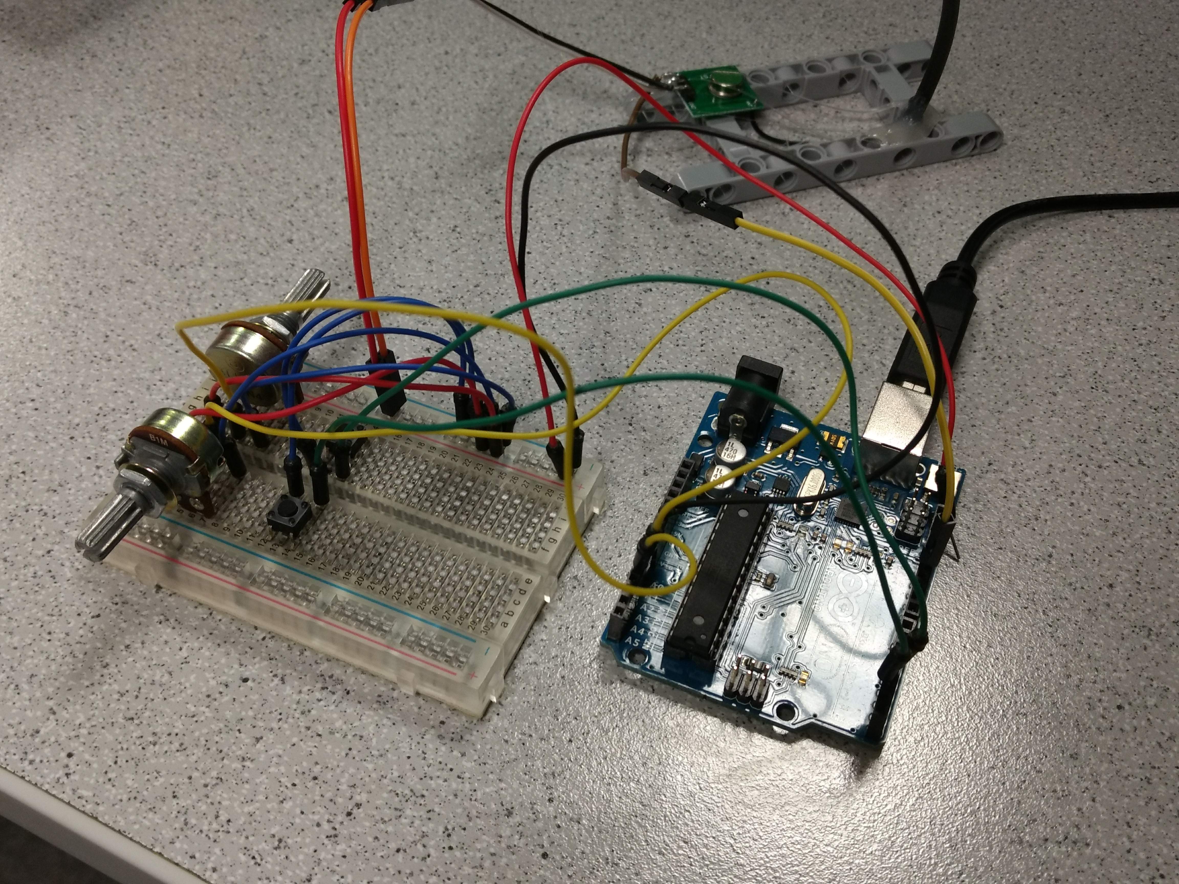
Oh and here's our thrown together RC controller (components explained in the next section).
Software
To test the electronics and the core functionality of the cars, we just wrote some basic code to send signals to the motor drivers.
The L298N motor H-bridge controllers are the perfect modules, because they allow bi-directional pulse-width-modulated control of each motor individually. In addition, the code is ridiculously simple, there are 6 pins that are connected to the driver board, and then depending on the states of these digital directions, you can select the different modes: forward, backward, off. In addition, the final 2 pins are used to "enable" each motor. This allows you to send a pulse-width-modulated signal down those lines to control the speed of the motors.
That test code can be found here.
Now that we could reliable control the direction and speed of the car, we decided to have a little fun with the cheap 433mhz radio modules which are really lightweight and easy to setup.
For this, we did have to use a library which implemented the amplitude shift keying procedure that allows a reciever and transmitter to communicate.
With the transmitter hooked up to another Arduino UNO and the reciever hooked up to the Arduino UNO on the car, we created a little test. It listens for input on the serial line and then sends that over radio to the reciever. The reciever then writes that message to serial. Unfortunately I didn't get a video of it working, but it was really neat because it was wireless communication of text without WiFi which we'd made ourselves.
Now that we had the communications working, we adapted the serial funcitonality to just sending bytes which were read from potentiometers and push buttons. These represented the motor speeds and motor directions respectively.
And with a little bit of C magic (final code here), we had an RC car.
In Action
Next Steps?
We hope to add a Raspberry Pi to the car so that we can control it over WiFi and then start writing complex algorithms, e.g. autonomous navigation.