

A Self-Balancing Robot
A two-wheeled balancing robot is is a fairly standard project idea. Seeing one for the first time on Kris Termmerman's YouTube channel (all his creations are awesome), I decided to give it a go.
I had left over stepper drivers from when I built my 3d printer, but unfortunately no spare stepper motors, so I bought some cheap ones from ebay.
I designed, then 3d printed, the frame for the robot.
Mechanically, it just needed to be strong to support the power of the motors and have enough room to mount a lipo battery and the electronics.
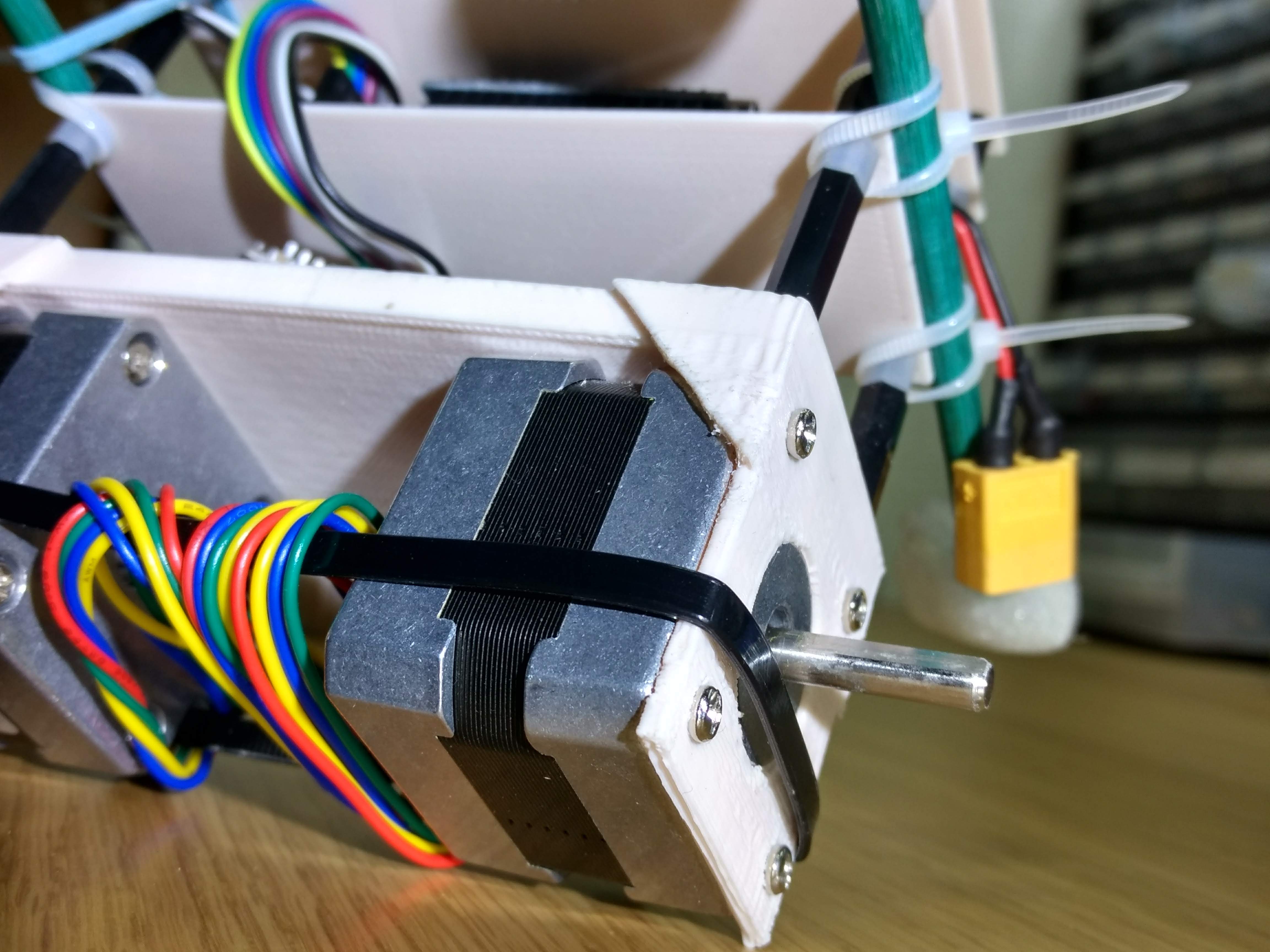
Here is a little shot of how the motors were screwed in:
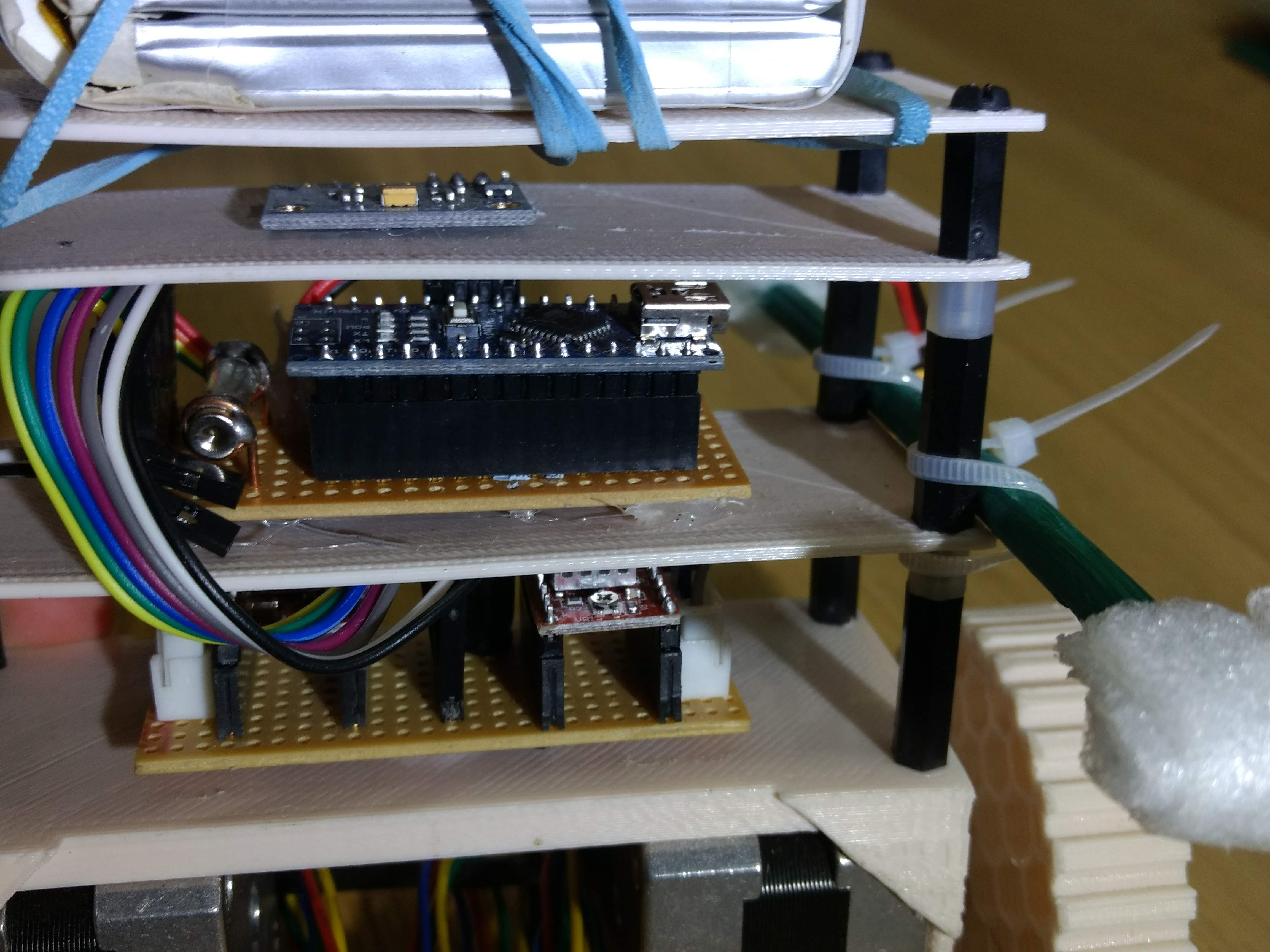
The design consisted of a series of layers (below) that were held apart by nylon standoffs. From the top down, I strapped a 3S (~12V) 1300mah lipo battery (that used to be for a quadcopter, but I broke the battery leads partially in a crash), an MPU-9250 accelerometer IMU unit, an Arduino Nano (popped into some headers soldered to a piece of stripboard along with a fuse and some male headers to attatch wires to the required pins) and then finally my custom power distribution board which I'll talk about later.
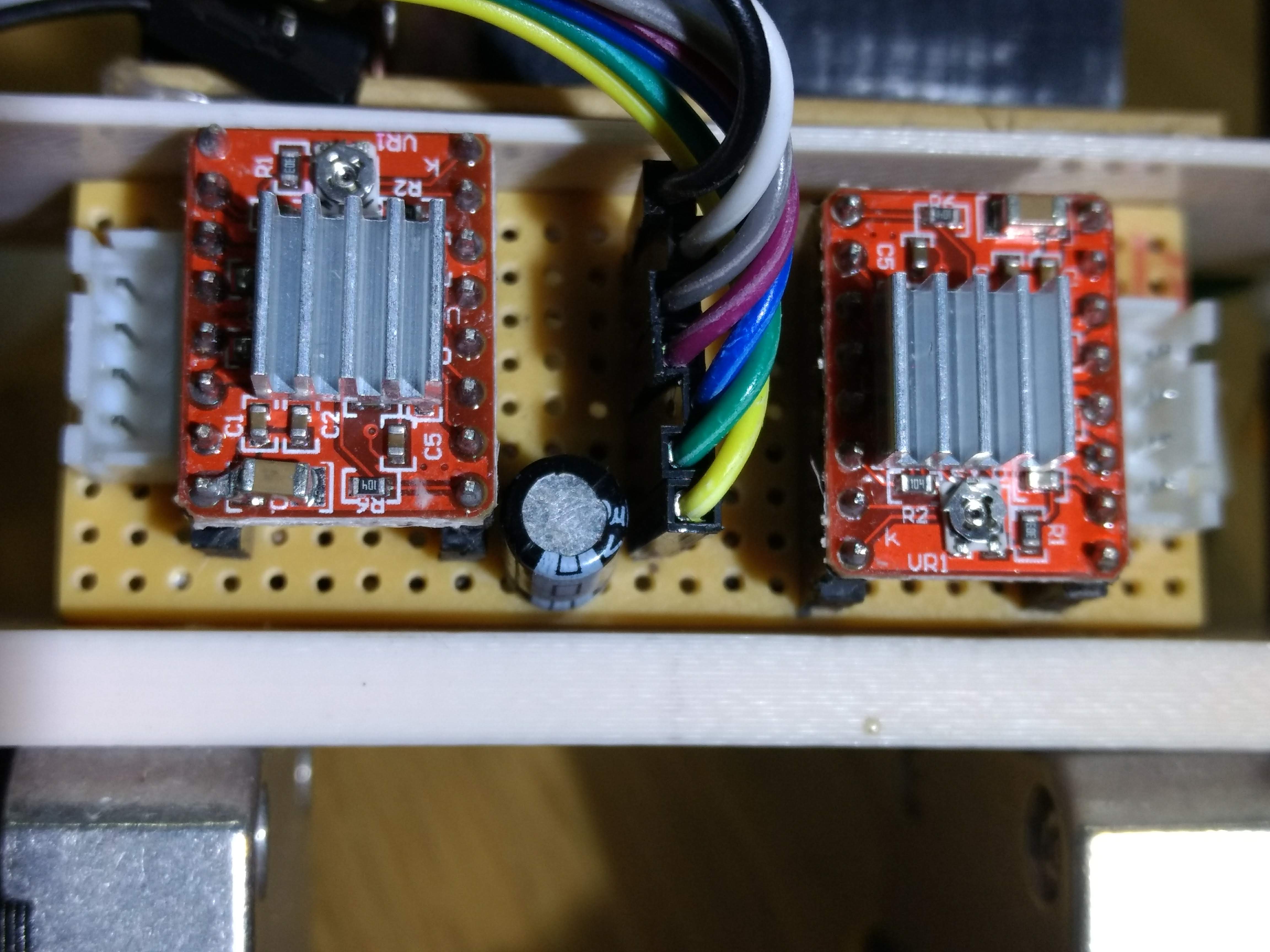
The driver board took quite a while to make, because there are a lot of things to take into account when working with the Pololu A4988 Stepper Driver. The main things are: the main power for the motors (from the lipo); a logic power supply (from the arduino's regulated 5V); a step pin that steps the motor when it receives a pulse; a direction pin, and then finally the four wires that connect to the stepper motor. There are also an additional three pins that allow you to prescribe the driving mode either: full, half, quarter, eighth or sixteenth step. Finally, you should also wire in a capacitor across the power supply to protect the electronics from backlash (voltage spikes from the motors stopping and starting).
Because there was so much to wire up, I created a dedicated power board that had headers that linked to the board that the arduino sits on and some 4pin connectors to plug the motors into. This can be seen below along with the lipo battery.
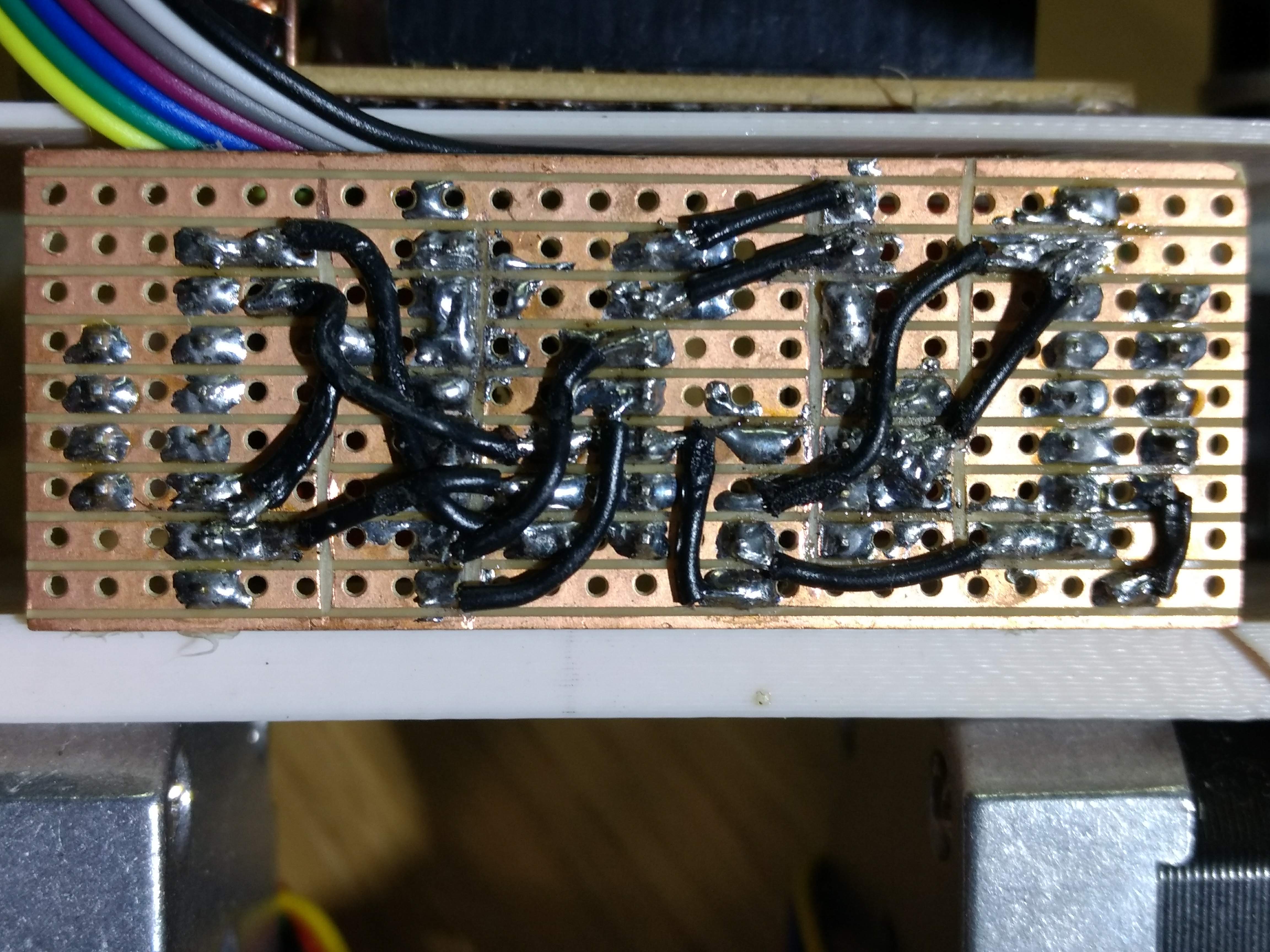
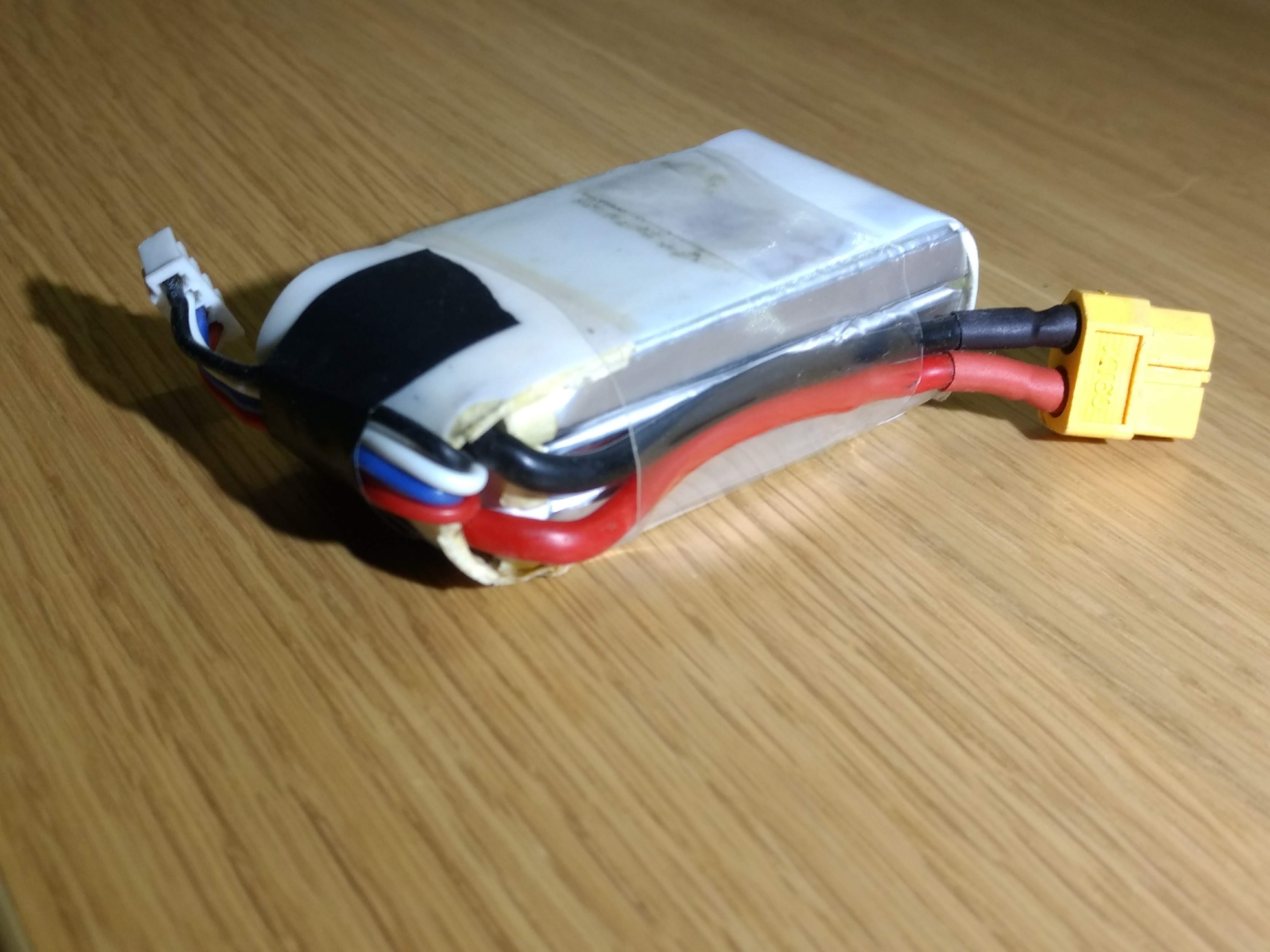
Note, this was taken mid-step-adjustment, so two of the wires are loose!
And that's it for the mechanical and electrical engineering, now for the software...
To make a robot balance, what I thought would be a "simple" PID loop is required.
However, the jittering from the stepper motor pulses caused high mechanical shocks that meant the readings from the accelerometer were very noisy.
This could be remedied by averaging, say 32, readings over a period of time.
I won't go into details about how I wrote the code, because there is lots online about how a PID loop works. If you are interested in my specific implementation details and how I interfaced with the accelerometer and the motor driver boards, then feel free to look at the code here on my GitHub (I've used some nifty tricks with unsigned counters and time deltas to efficiently calculate when to pulse the motors).
I then spent hours tuning it - at one point I wrote an addition to the code that streams all the sensor data over serial back to my laptop after a test, since streaming data during a test changed the behavious of the robot. I also improved its grip by wrapping the wheels in a couple of rubber bands.
Eventually, it could balance:
I'd like to have got it driving about, but the motors didn't quite have enough speed to counteract big wobbles, and bigger wheels lacked the torque to rotate the heavy mass, this meant I never got to the stage of having it actually drive about. I also tried moving the lipo to be in-line with the motors, so the centre of mass was lower and it would required less effort to rotate, but this still wasn't enough.
If I had money to spare, I could invest in faster, higher torque motors, but nevertheless it was a fun project and I learnt a lot about stepper motors.