

My second attempt at building a robot arm (very violent).
If you haven't seen my first arduino robot arm, then please checkout that project here. The idea of that project was a test of what was possible using servos and an arduino. I wanted to see if I could build a strong, accurate and repeatable robot arm and I think I succeeded in doing so shown by that video. However, I spent no time planning or thinking through the design, I was just foccused on the one goal of picking and dropping stuff down a slide. This led to me building the frame out of some weak wood and having a bad bottom axel where the whole weight of the arm was resting on the flimsy plastic servo at the bottom.
After finnishing it, I realised that the project had potential but to do anything more substantial, I would need to spend more time on its design and use different motors. I researched in-depth the different ways robot arms could be configured involving things like their degress of freedom, max torque and there working area. If you are interested, checkout this introduction. Anyway, I settled on bulding an articulated robot arm which allowed for the most versatility and degrees of freedom.
Anyway, after wasting some time watching these things on youtube, I realised that one of the key design points was the motors used. As before, I had decided to use servos but the small TowerPro mg90s weren't going to cut it as they have plastic gears and hardly any torque. So I came across this website called the servo database where you can sort a huge variety of servos based on torque, weight etc. Eventually, I decided that I would use the mg996r servos. They have 9.6kg/cm torque and are metal geared so they would be perfect for my application. So knowing that they would take a while to arrive, I ordered 4 for £13 off ebay. In the meantime, I began the design of the arm...
As this was going to be a bigger project than my last robot arm, I needed the design of the arm to be much stronger and stable so I decided to 3D print it. I am not going to go into the stages of design here, but you can find the finished model files and view them here.
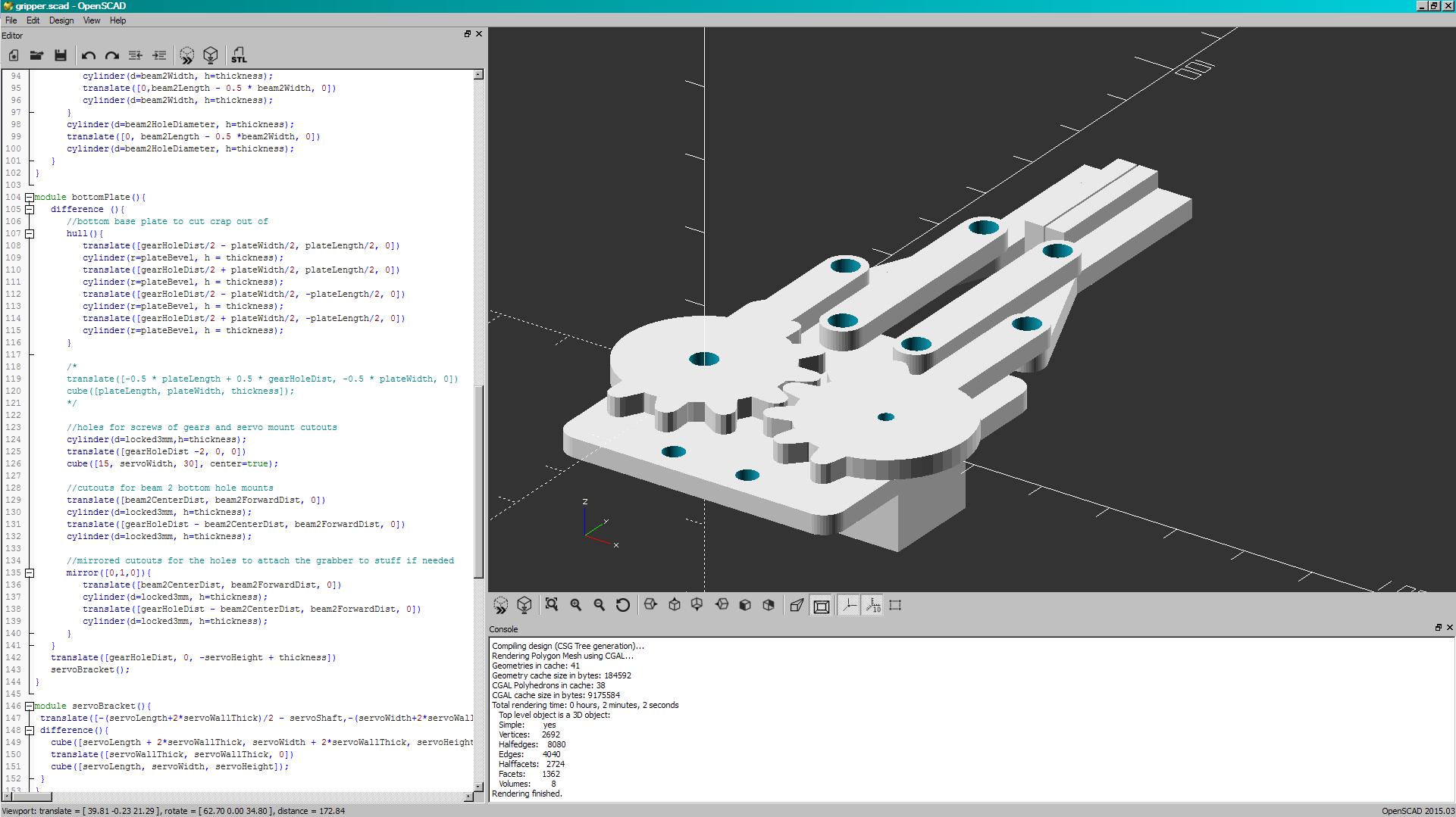
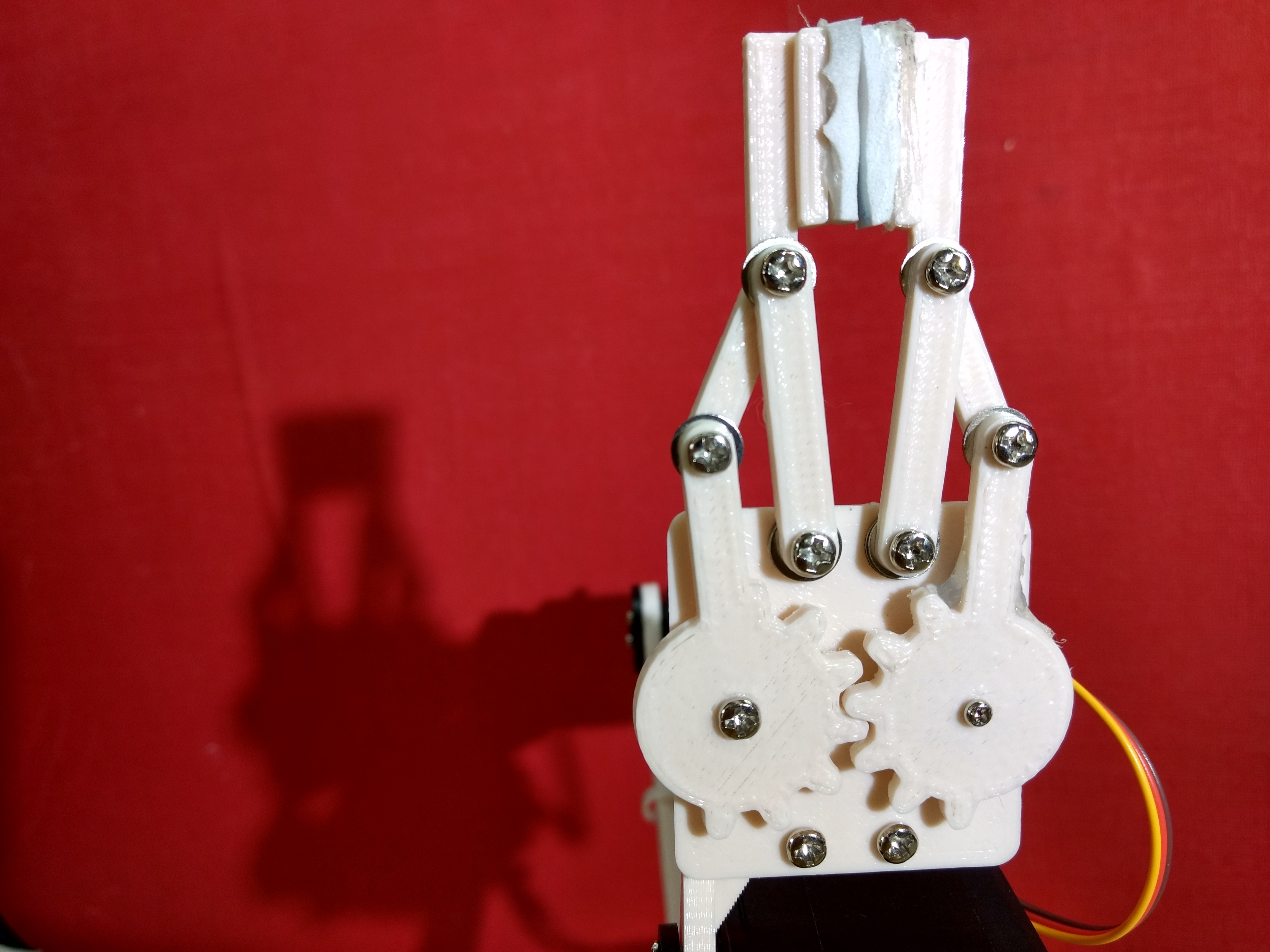
When I have the time, I will write some posts on openSCAD and 3D printing in general, but I thought it might be interesting just to put in a screenshot of the most intricate part of the design - the gripper. This took many revisions to get right but works really well.
Finally, once I had finished the design of the frame, I printed them out and put the thing together with the servos. Here it is:
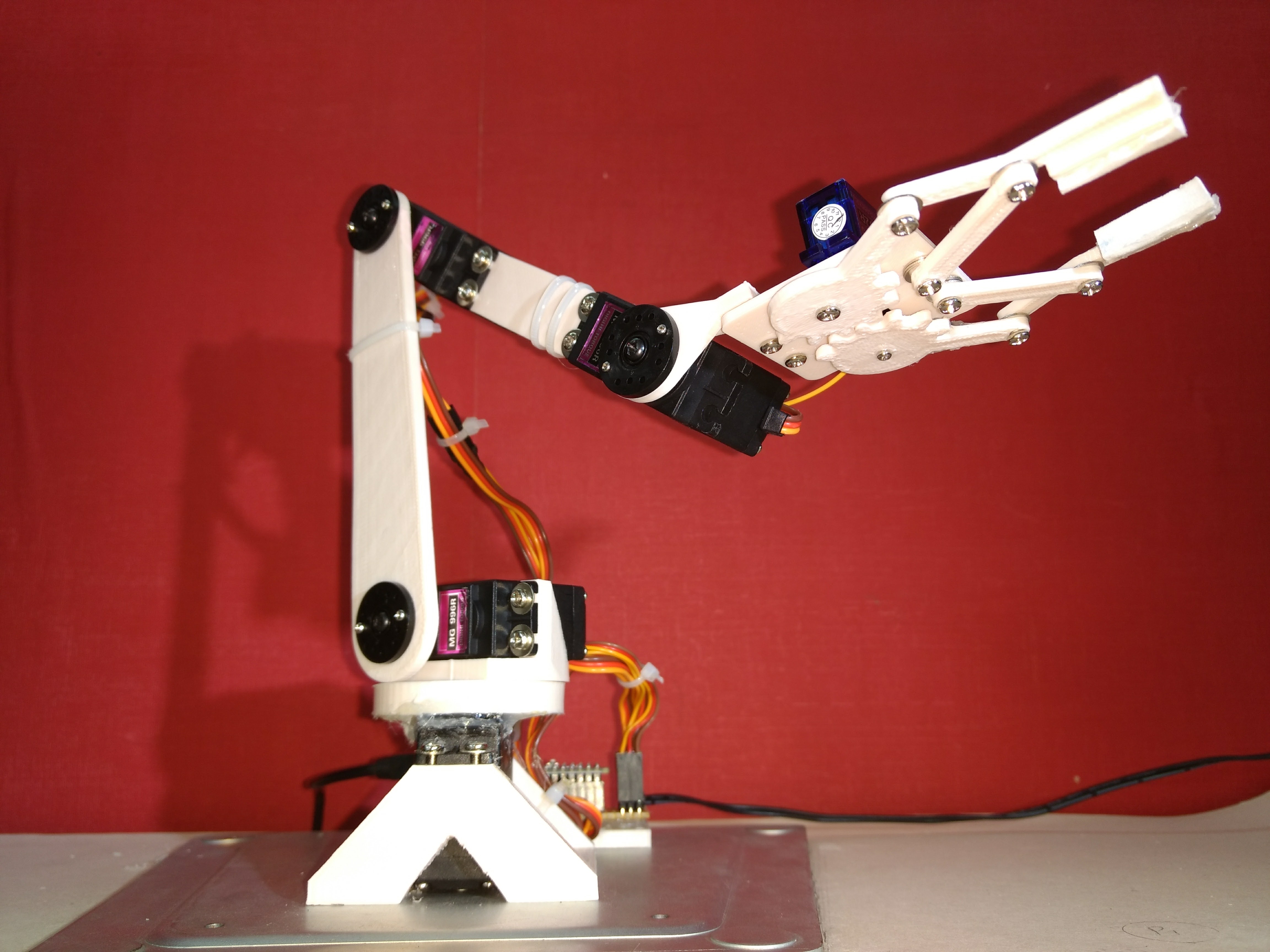
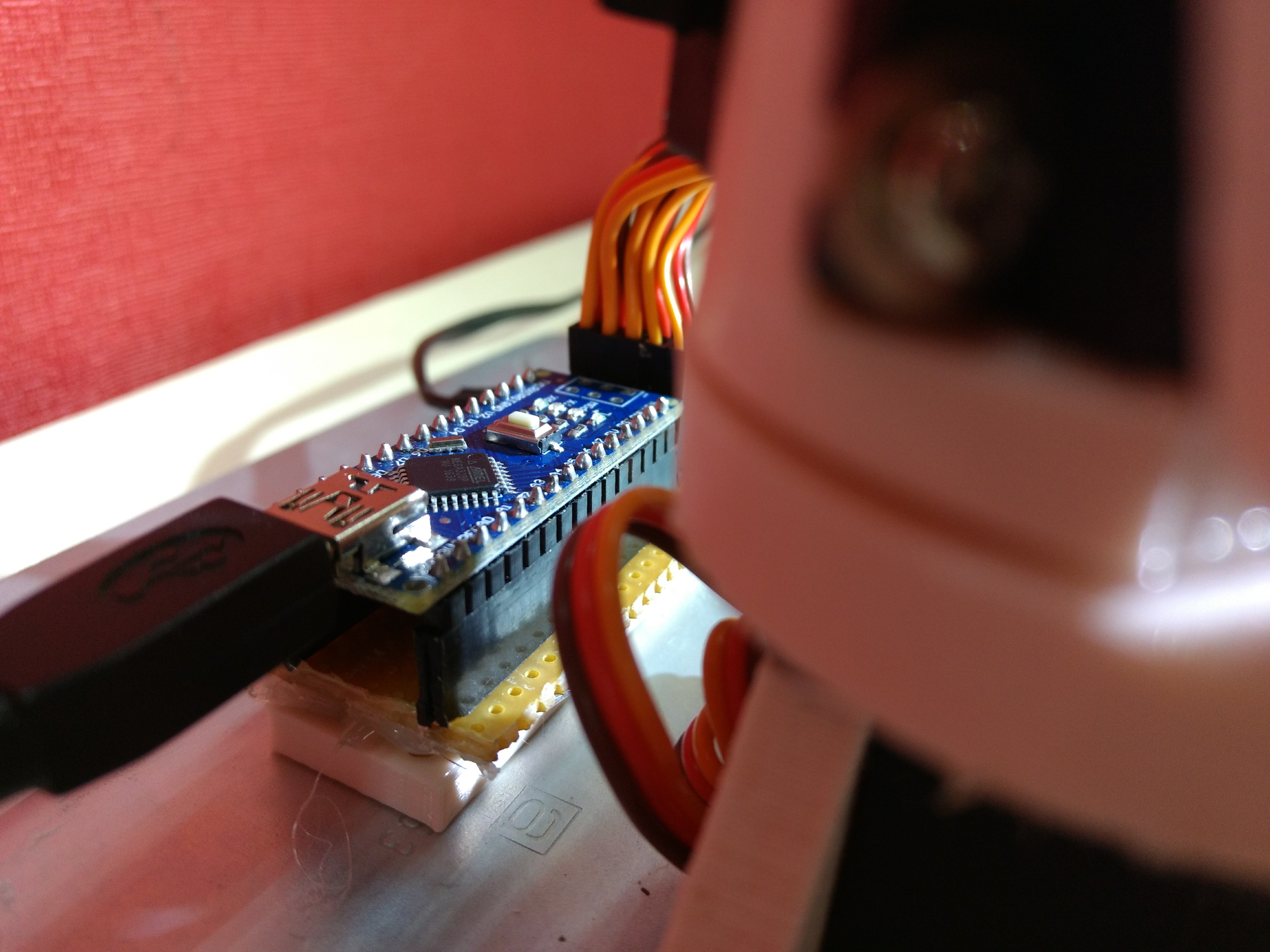
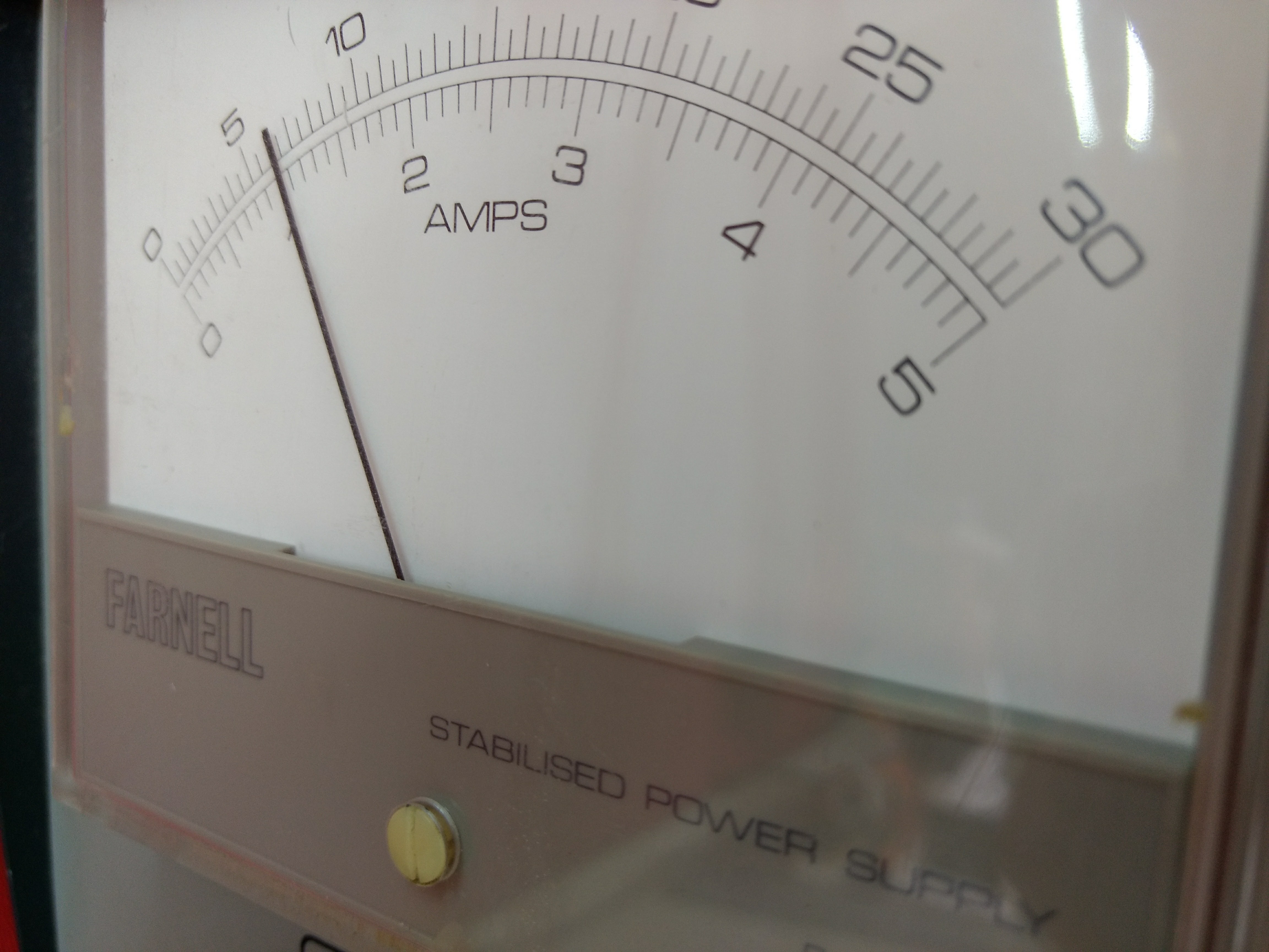
The actual design is now obvious and I was pleased with how it came out. I then soldered together a mini circuit board which just had some headers for the servo leads and for the arduino nano I used to program it. I had to setup the servos power to come from an external 7v power suppply (bottom) because they drew a lot of current which the arduino wouln't have been able to handle.
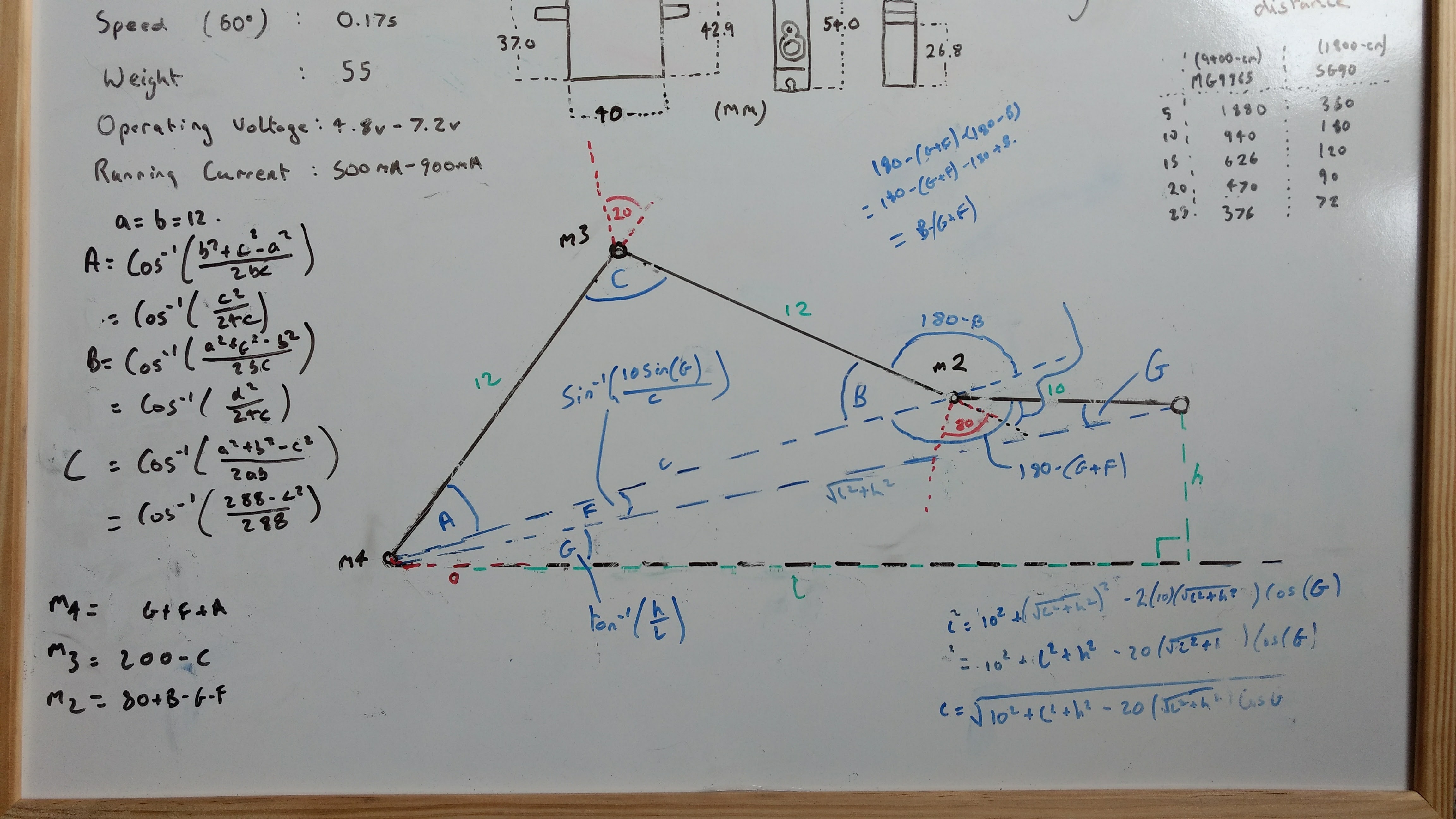
I then began programming some tasks for it and testing its limits through the Arduino IDE. In the process, I created a Serial program which would accept ASCII chars and convert these to postions for motors. However, this became tedious and for instance when I wanted to move the gripper forward, it would mean decreasing motor 4 and increasing motor 3 (motor 5 being the bottom motor). It would be preferable for me to be able to program it in terms of distances from the center say a length, height and rotation angle. This meant some looking up inverse kinematics and doing some trig. These are my final calculations (the final ones are in the bottom left):
Now I had a good way of controlling the motion of it, I could hardcode some set positions and get it to move between them. This got me thinking of a relatively simple task I could get it to do. I decided on chess. More specifically, I set me goal to be getting it to setup a chess board. Something that proved to be quite difficult...
Here is a short video of one of its first attempts at setting up just the pawns.
Baring in mind that I had to manually control the arm to each position working out where everything should go, this wasn't too bad an effort. But I knew that if I had to do this for all the other pieces and improve the current motor angles for the pawns, that this would take a while.
So in an effort to speed up the process, I put the project on hold and created a user interface to control the robot with. I coded a it in python using the TkInter GUI and the pyserial library. I had briefly used the TkInter library before so that wasn't too difficult, but I knew that serial communication between python and the arduino would be hard. As all I needed to send to the arduino was motor positions, I could neatly send them one by one as bytes up to an arbitary newline '\n' char for simplicity (ascii 10). As the motor values can range from 0 to 180 degrees, a byte would be perfect as they can store 8 bits so any value from 0 to 2 ^ 8 or 255. I then first modified the arduino sketch so that it read from the serial buffer storing each byte it heard up to a newline in an array before writing them to the motor positions. After, I wrote the python side which just sent the ascii of each motor position from the tkinter script. This was easy as python has a built in function chr() which converts an int to an ascii charachter. So for each motor position, I converted it to a chr for example 90 which is the center position would be a capital z ('Z') and wrote it to serial with the pyserial library followed by a final newline ('\n'). One last thing I had to take into account was that the arduino may not be able to handle all the positions if sent too fast and the serial buffer would fill up. So to solve this I just sent the positions at 5ms so the arduino could keep up.
This was the finnished result:
Finally I had an easy way of setting the arm in differnt positions so I got to work neatening the pawns and making the positions for the back line pieces. Unfortunately though, I accounted a new error - my robot had Parkinson's disease. At a distance, the weight of the arm meant the second from the bottom (number 4) motor got into a PID control loop and began oscilating. As a result, picking up pieces at a reach like the queen and the king proved difficult and the arm had poor repeatability at that distance. Anyway, I continued on and this was the final result. Not perfect but the best it could achieve.