
Coilgun
WARNING NOT FINISHED
The Theory
This project is my proof-of-concept coilgun (uses one or more electromagnets to launch a projectile at high speeds).
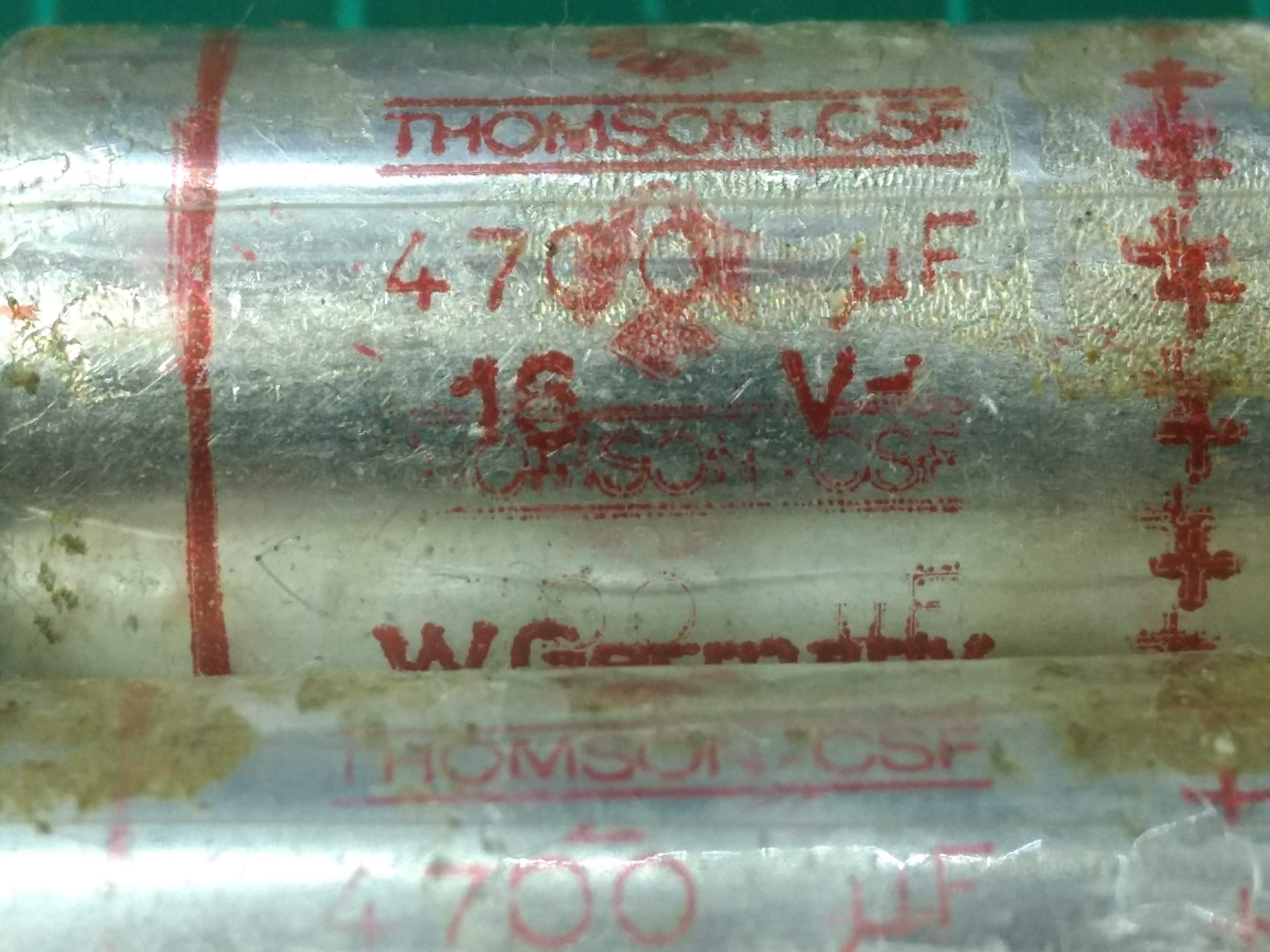
When digging in some old electronics, I discovered some fairly large (\(47,000μF\)) capacitors. I used this as an opportunity to learn about capacitors and their uses.
Previously, the only application of capacitors I was aware of was their use in smoothing voltage lines. I knew qualitatively of them as "buckets" that will store up charge, and then release or absorb it gently whenever a voltage spike occurs which "smooths" the line. I had also seen the log-type graph of a capacitor charging in series with a simple resistor on an oscilloscope briefly, but didn't have the chance to explore this much further. Other than that, I had used them in a couple of Arduino projects, but overall didn't have a good understanding of them.
After some research, I had a bit more of an idea - all they are comprised of are two very large conductive plates separated by a small distance via an electrolyte. Capacitors store energy via collecting charge on one one of the two plates (unlike inductors which store energy via creating a magnetic field). The charge is stored when a potential difference is applied across the capacitor - an electric potential causes electrons to be pulled in a current from one plate to the other, but since they cannot make it across the dielectric, they deposit on one of the plates, resulting in a difference in charge between the two plates.
I tried making one but I would need a much better electrolyte and larger plates to create anything with a meaningful capacitance.
Getting back to my application of capacitors...
We want to transfer as much energy as possible to the projectile as fast as possible. Large capacitors are clearly ideal for this as they can store the charge and then release it at effectively infinite current. This is in contrast to a power supply that, although it may be able to supply it for longer, can only provide a couple of amps. Let us do some extremely rough calculations to support this idea...
My power supply, can deliver an absolute maximum \(30V\) at a constant \(2A\). This is a power of \(60Js^{-1}\). If we assume \(1\%\) efficiency (small, but that's the really of what people talk about online and it's only going to be bigger for smaller scale experiments) and that the projectile spends \(0.01s\) within the electromagnet, then the kinetic energy transferred to the ball is something of the order \(0.1 * 0.01 * 60 = 0.06J\).
Now let's compare that with the energy supplied by three of the \(47,000μF\) capacitors in parallel.
Charge, \(Q\), capacitance, \(C\), and voltage, \(V\) are related by: $$Q=CV$$ And energy transferred is given by \(W=\frac{1}{2}VQ\) because as the capacitor discharges, its potential difference decreases linearly, so the total work is \(\frac{1}{2}\) a battery supplying the same amount of current, but at the fixed voltage which the capacitor is initially at. See here for a much better explanation. So overall we have that: $$W=\frac{1}{2}CV^2$$ Capacitance obviously adds in parallel for capacitors as their plates are essentially just glued together. This means \(C_t = 3C = 3 * 47,000 \approx 150,000\mu F \approx 150mF \approx 0.15F \). The capacitors are rated for \(16V\), so assuming the same \(1\%\) electrical efficiency, we have a much larger kinetic energy of \(0.01 * 0.15 * 16^2 = 0.384J\).
This is \(64\) times more kinetic energy, so would theoretically correspond to \(8\) times more velocity since \(v \propto \sqrt{E_k}\).
However...
The real beauty of the capacitor method is that the length of the coil can be adjusted so that the capacitor discharges exactly as the ball is halfway through the coil. Without this, the ball would be decelerated as it passes through the second half of the electromagnetic field. So even a more powerful power supply would be useless as the ball should exhibit dampened oscillations about the centre of the coil (mine just meekly rolls the ball to the centre and then holds it there). So, yes, in much more powerful coilguns, with multiple coils for example, additional electronics with timers, MOSFETs and other switching components are required to time it so coils are only activated when the projectile is in the first half of each coil, but for my simple demonstration it works out excellently that the capacitors automatically "run out"!
Since we may as well, we could also calculate the time for the capacitor to discharge and thus estimate a rough order-of-magnitude length for our coil.
The time constant, \(\tau\) of a capacitor is the product of the load resistance and the capacitance: $$\tau=RC$$ Note: this constant is just a useful value to assign our circuit because it is immediately apparent in the equation for the exponential decay of a capacitor as it discharges.
The voltage across the capacitor is given by the equation: $$V=V_0e^{-t/RC}=V_0e^{-t/\tau}$$ This is clearly an exponential decay, as \(V \propto \frac{1}{e^t}\).
We can see that with our electromagnet, which has a resistance of \(0.58\Omega\), and the parallel capacitor arrangement described previously, \(\tau=0.58*0.15=0.087s\). We see that after a time of \(t=5\tau=0.435s\), and an initial voltage, \(V_0=16V\), the voltage across the capacitor is \(16e^{-5} \approx 0.1V\). So after just half a second, our capacitor will be almost entirely discharged. We may also observe that after a time of one time constant, \(t=\tau\), the voltage drops to \(e^{-\tau/\tau} = e^{-1} \approx 36.8%\) of its initial \(16V\) which is \(\approx 6V\). So in less than a tenth of a second we have already dissipated way over half of the energy stored in the three big capacitors.
Now time for some extremely rough estimations just to show the calculations are about right... If the ball, of a mass about \(1g = 0.001kg\)... calculations need adjusting to make this work!!! Maybe as small as 0.1% efficiency?? See gphotos for diagram on projectile motion to estimate muzzle speed of ball. See gphotos for diagram on projectiles ^^ See gphotos for diagram on projectiles See gphotos for diagram on projectiles
Design and Tests
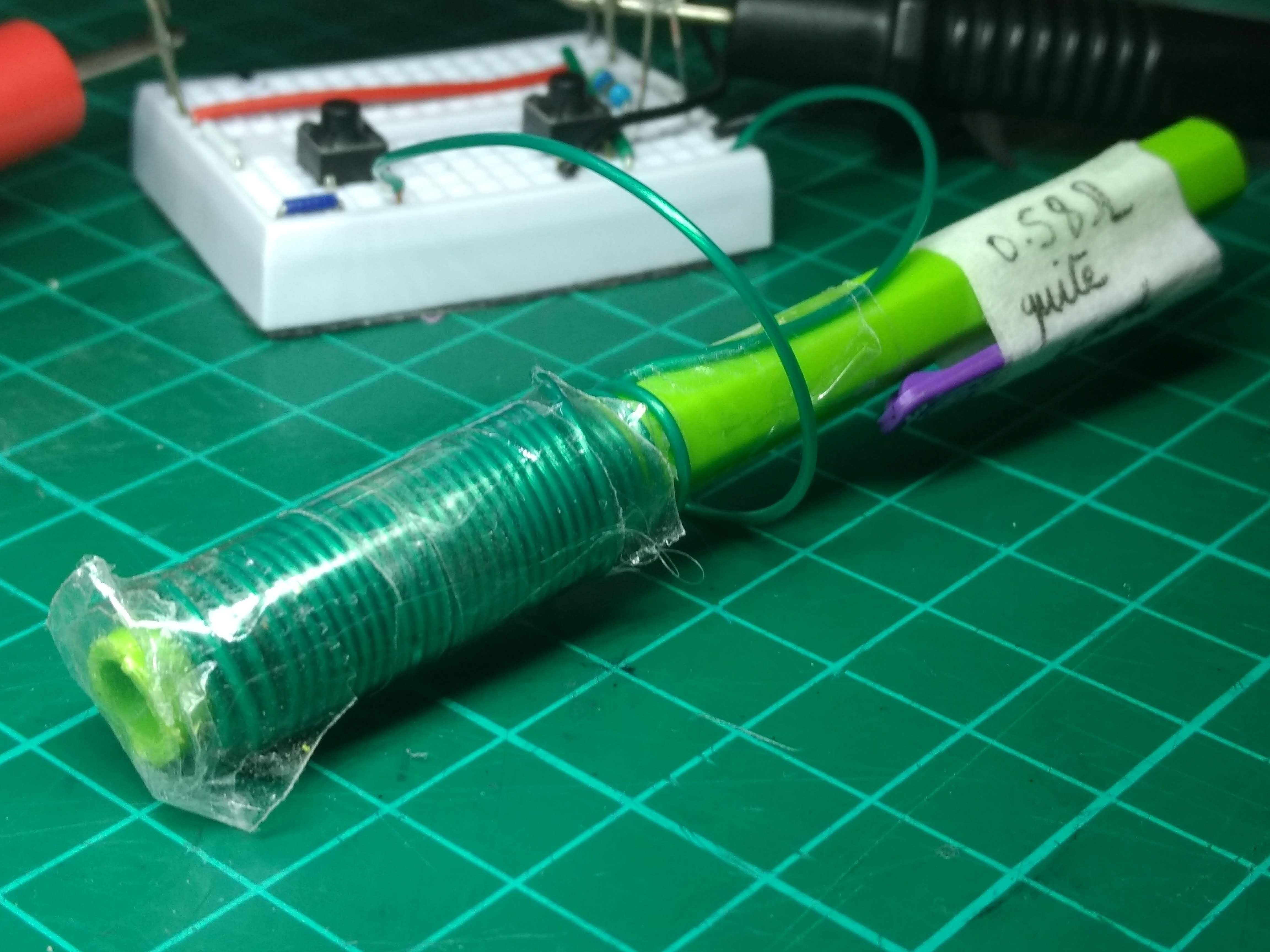
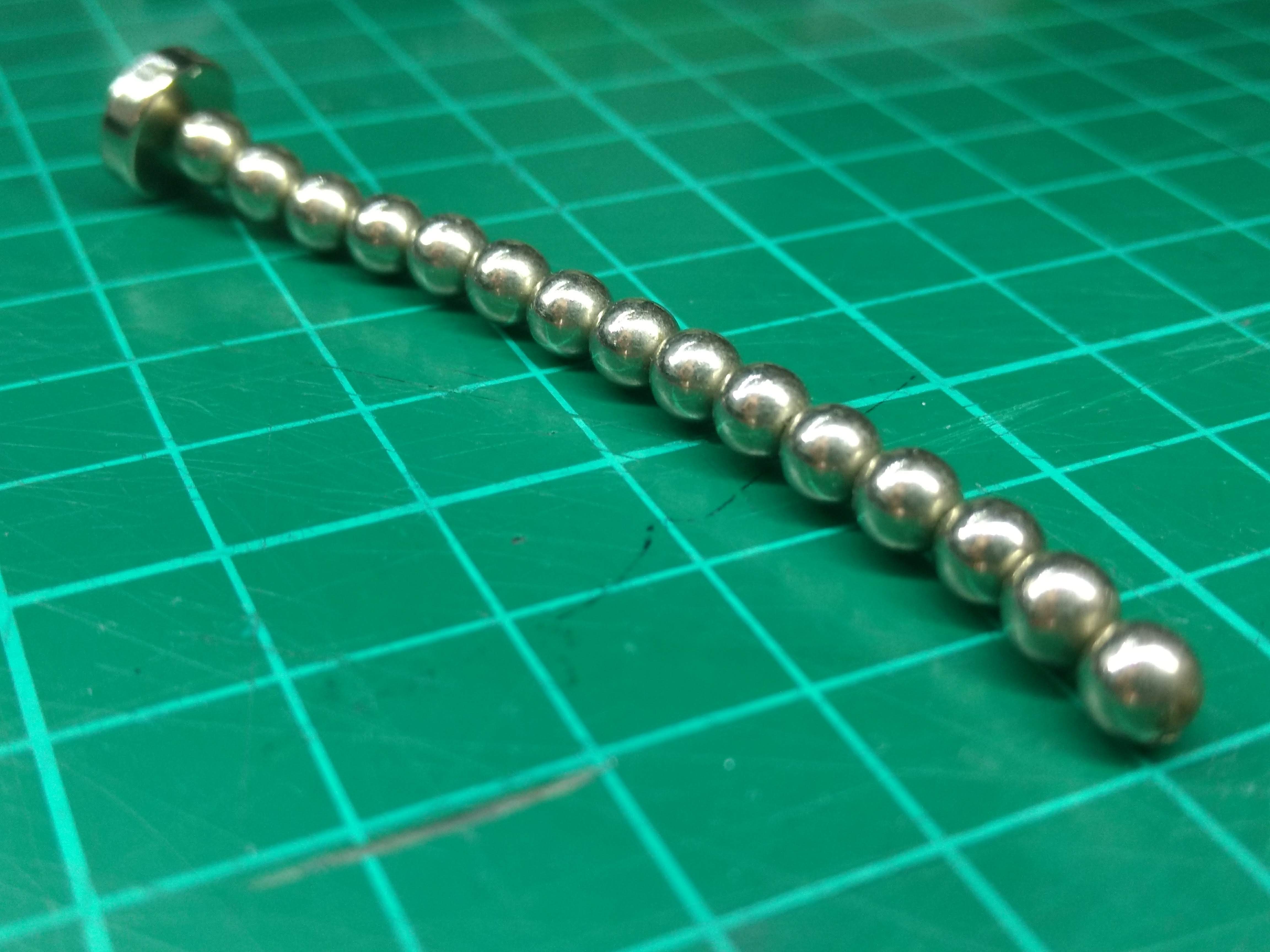
For the projectile, I used a small spherical neodymium magnet. For the barrel I used the outside of a plastic mechanical pencil. As seen in the video at the end, a second magnet was used to correctly align the projectile's permanent magnetic field with the temporary magnetic field created (this was determined experimentally as the projectile launches much further when it is aligned correctly than when it is aligned randomly or the completely wrong way around.
The electromagnet was wound with about \(50\) turns of insulated copper wire. I experimented with different gauges and turns of wire and the optimal turned out to be a coil with a length of \(\approx 4cm\) which resulted in a resistance of \(0.58\Omega\).
To do a couple more t
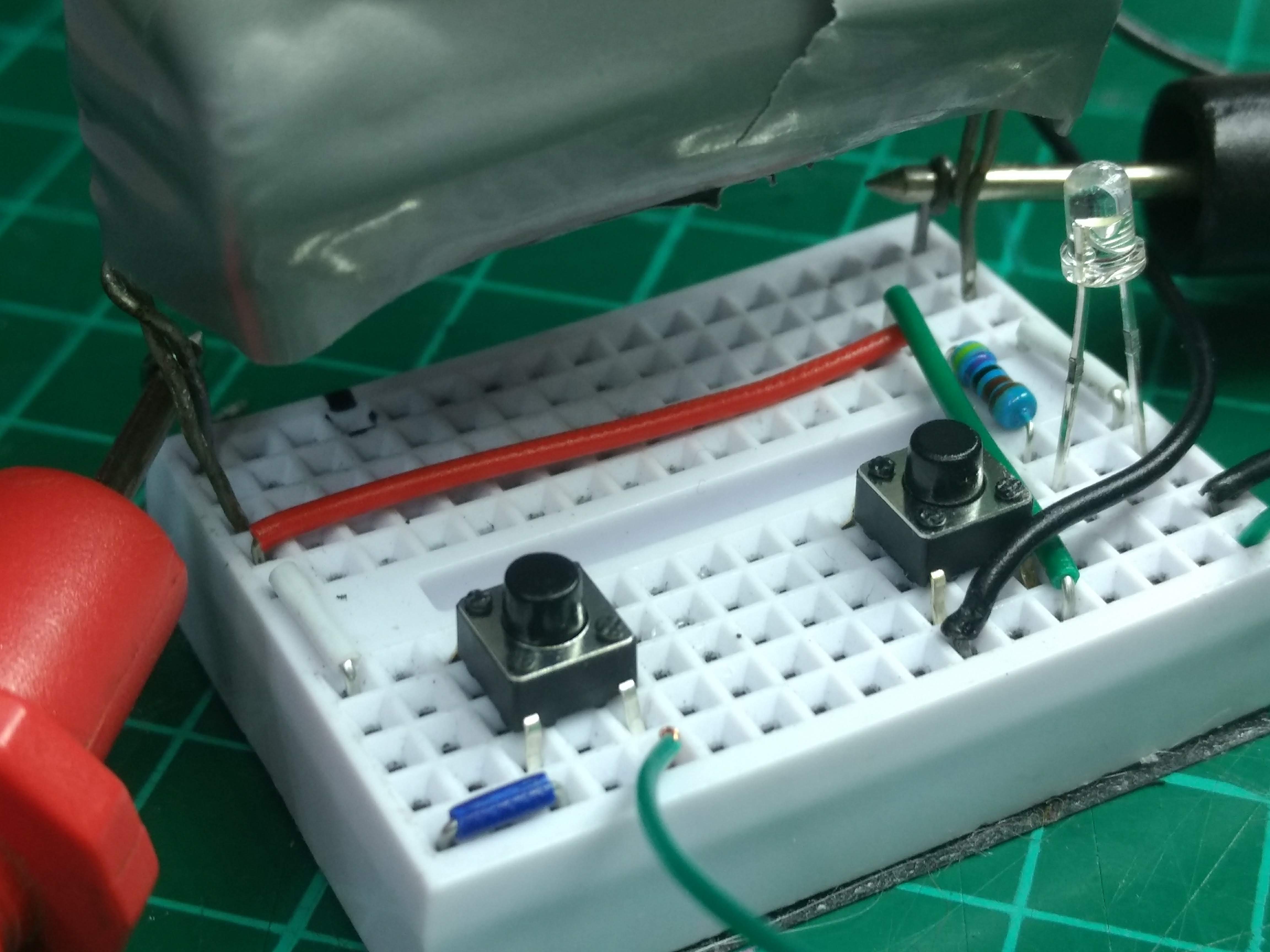
Draw a circuit diagram and insert here