
Useless Box
Having seen these boxes floating around Thingiverse (a site where people share their designs for models to 3d print), I thought I'd try make one myself.
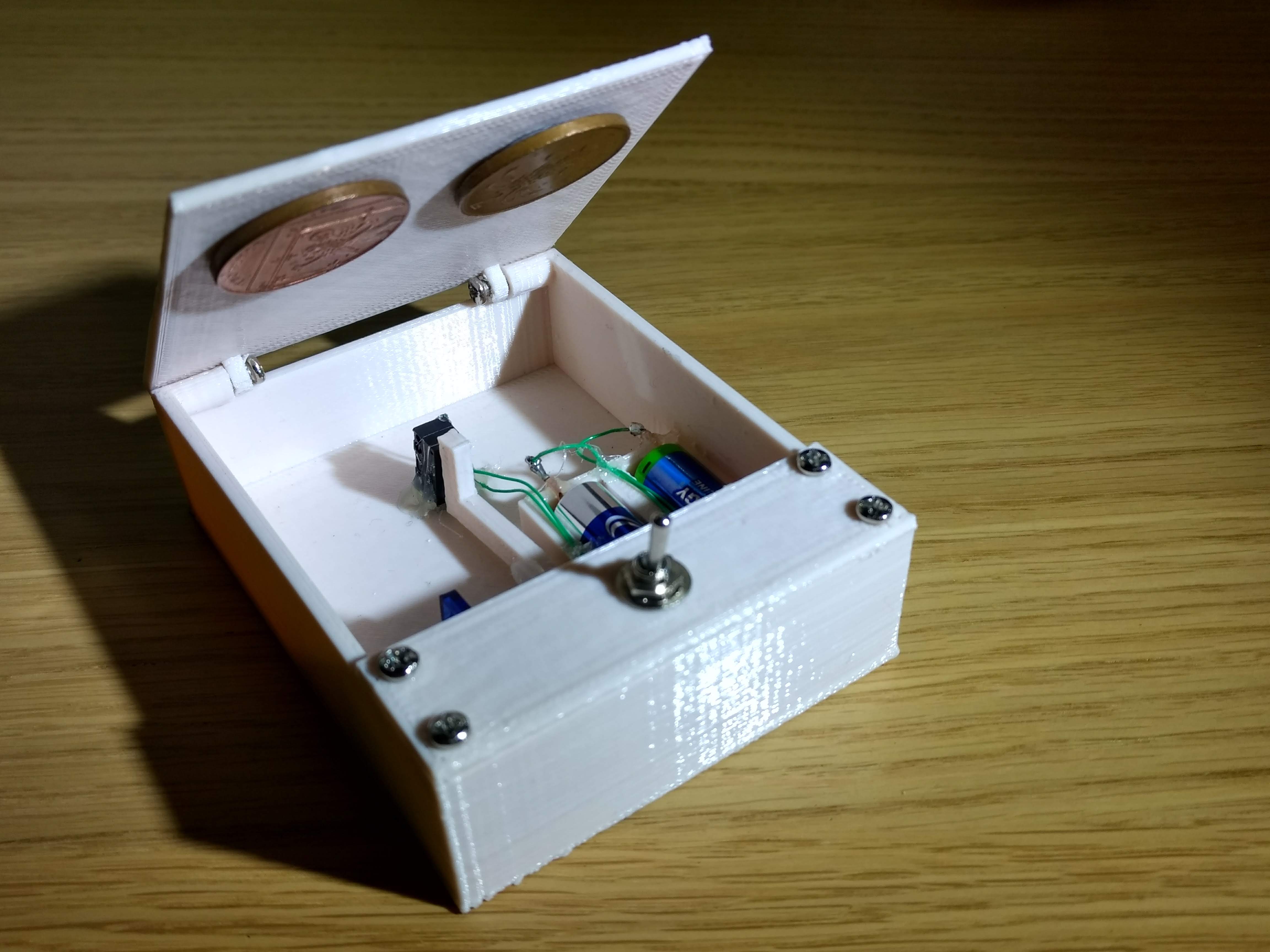
The basic idea is to hide a servo, batteries and switches inside a box so they are as concealed as possible. Then when the main switch is flicked, it will start the DC Motor in the servo moving towards the main switch. Then when the switch is flipped by the servo arm, the direction of the motor will be reversed so that it is now moving back down towards the bottom of the box. It will then stop when it reaches the endstop switch which is wired in such a way that it is open when pressed so the circuit is broken when the arm reaches the resting point.
By having a weighted hinge, the servo will be able to push through the lid, flick the switch, and then the lid will fall back down when the servo returns home.
Here is the useless creation in action:
The design process
As usual I used OpenSCAD to make the design for my 3d printer (I'll make the code available on Thingiverse at some point).
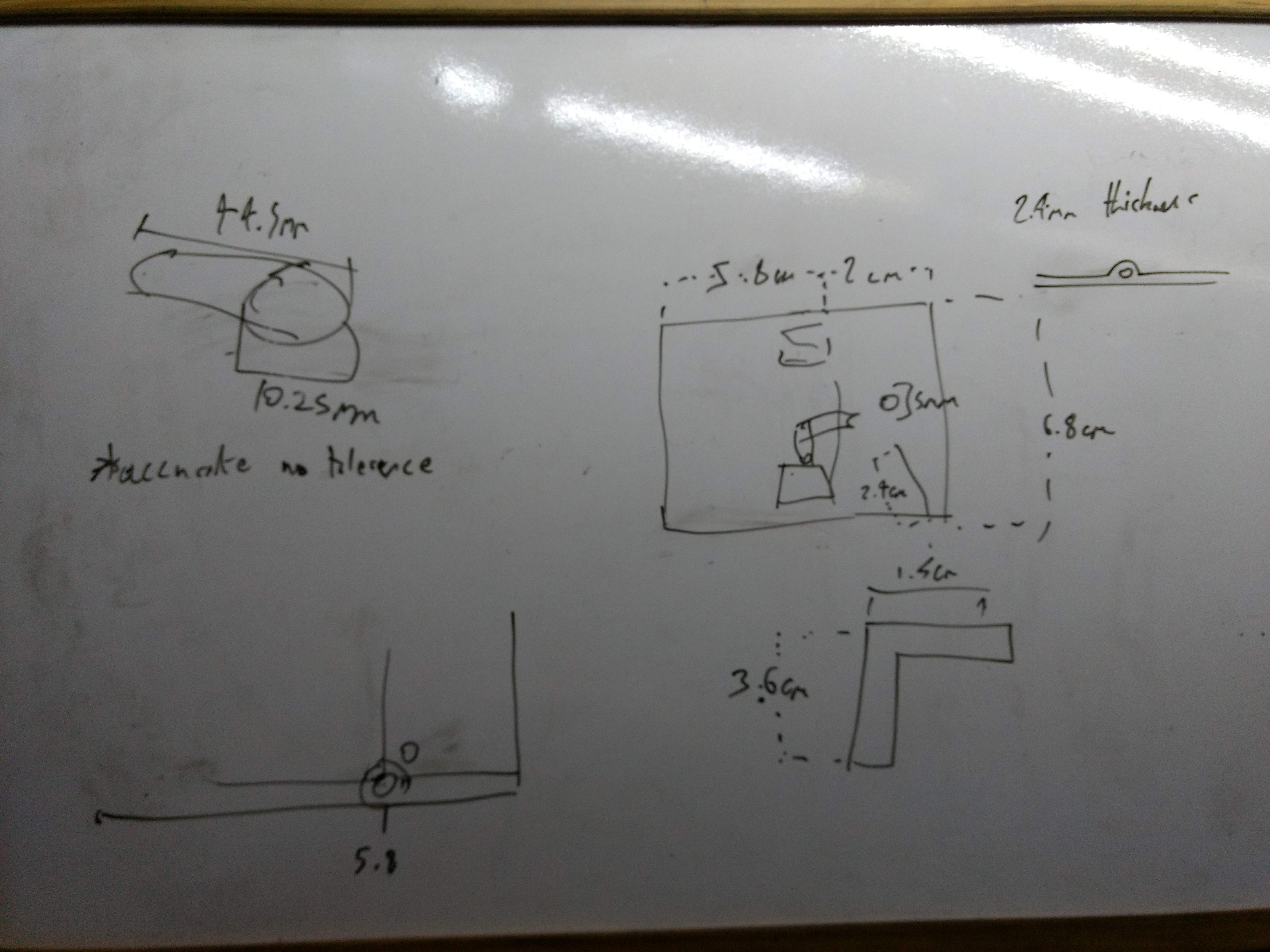
This is my extremely scientific design:
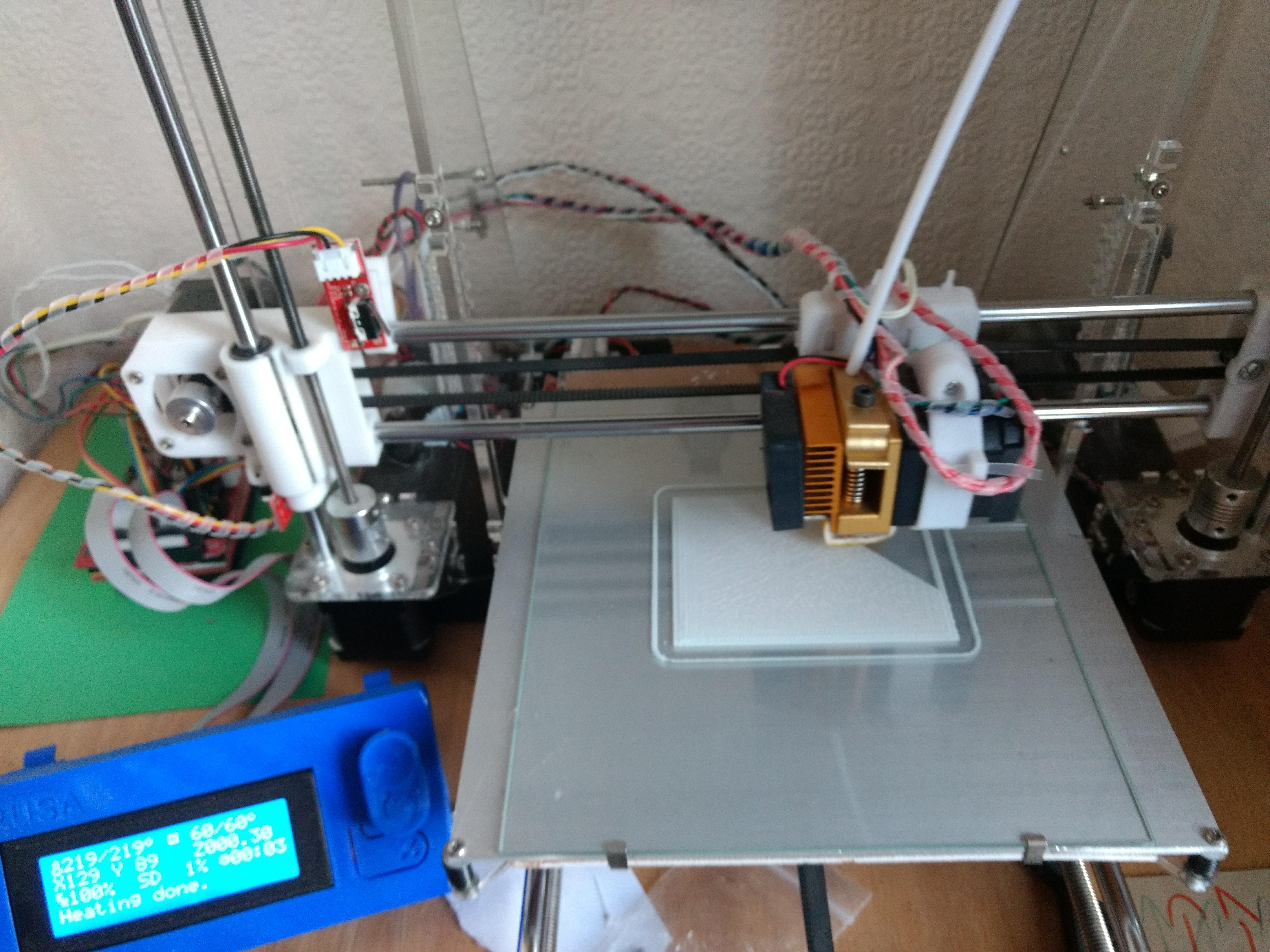
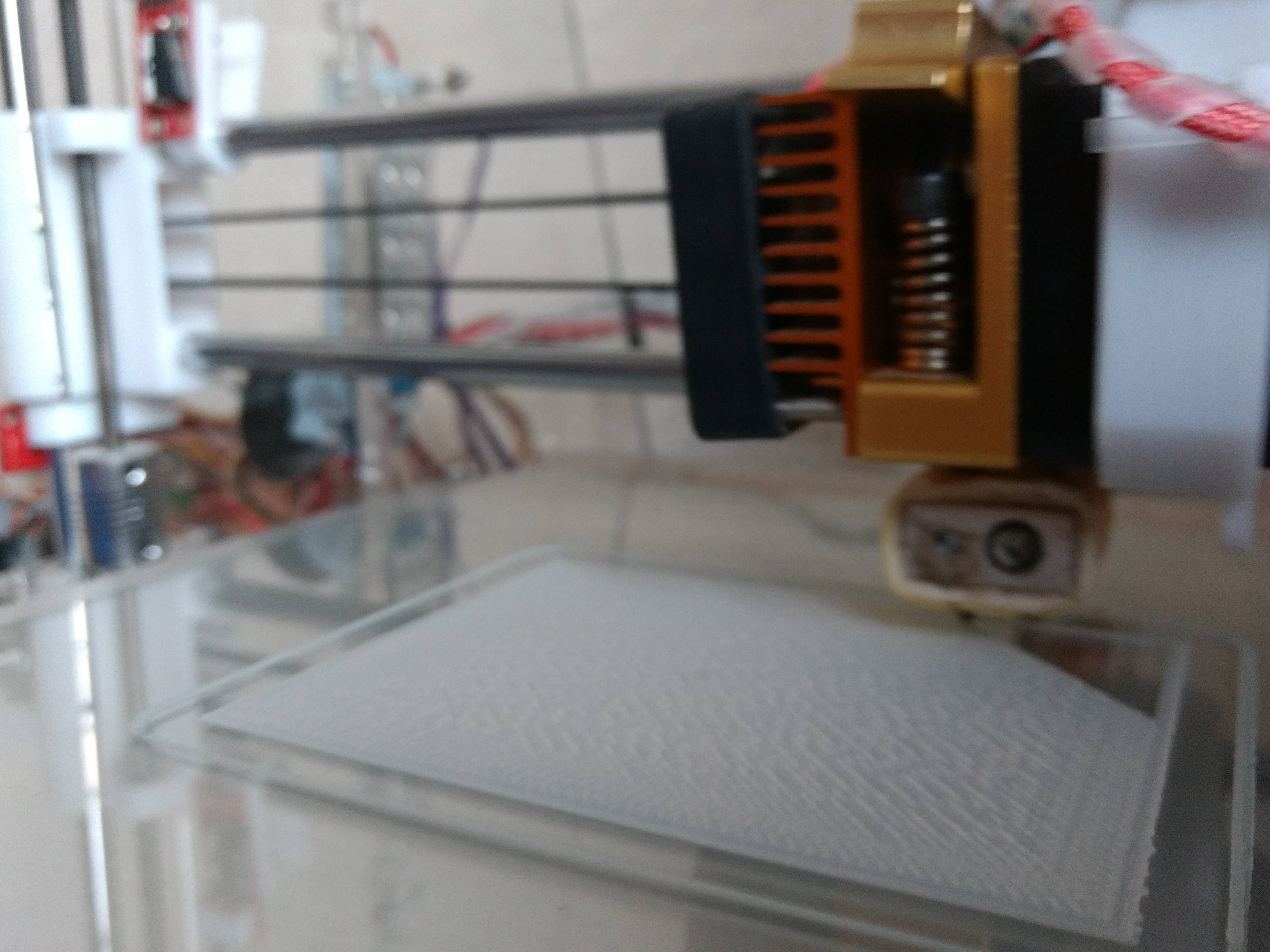
Here are some images of it printing:
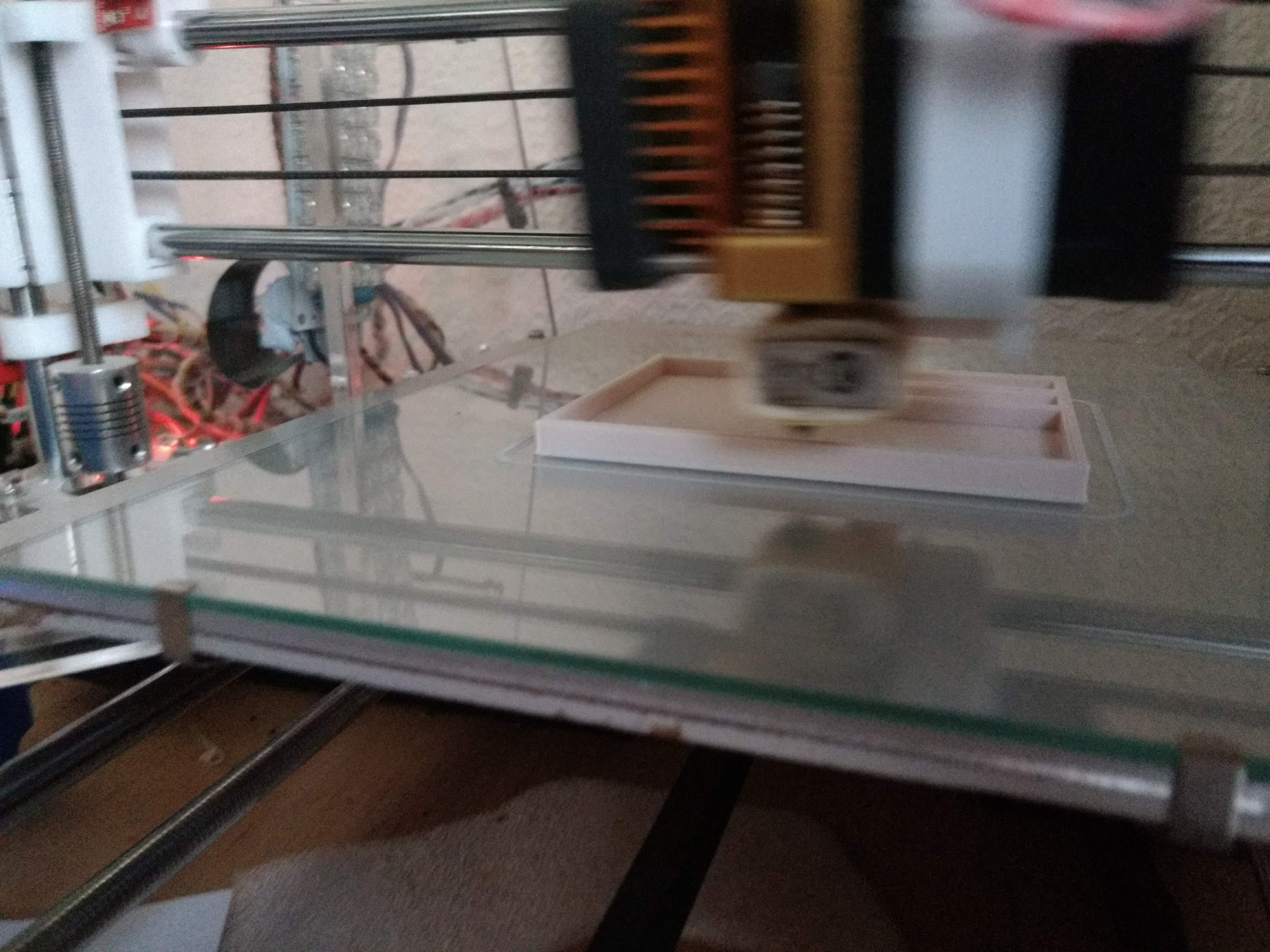
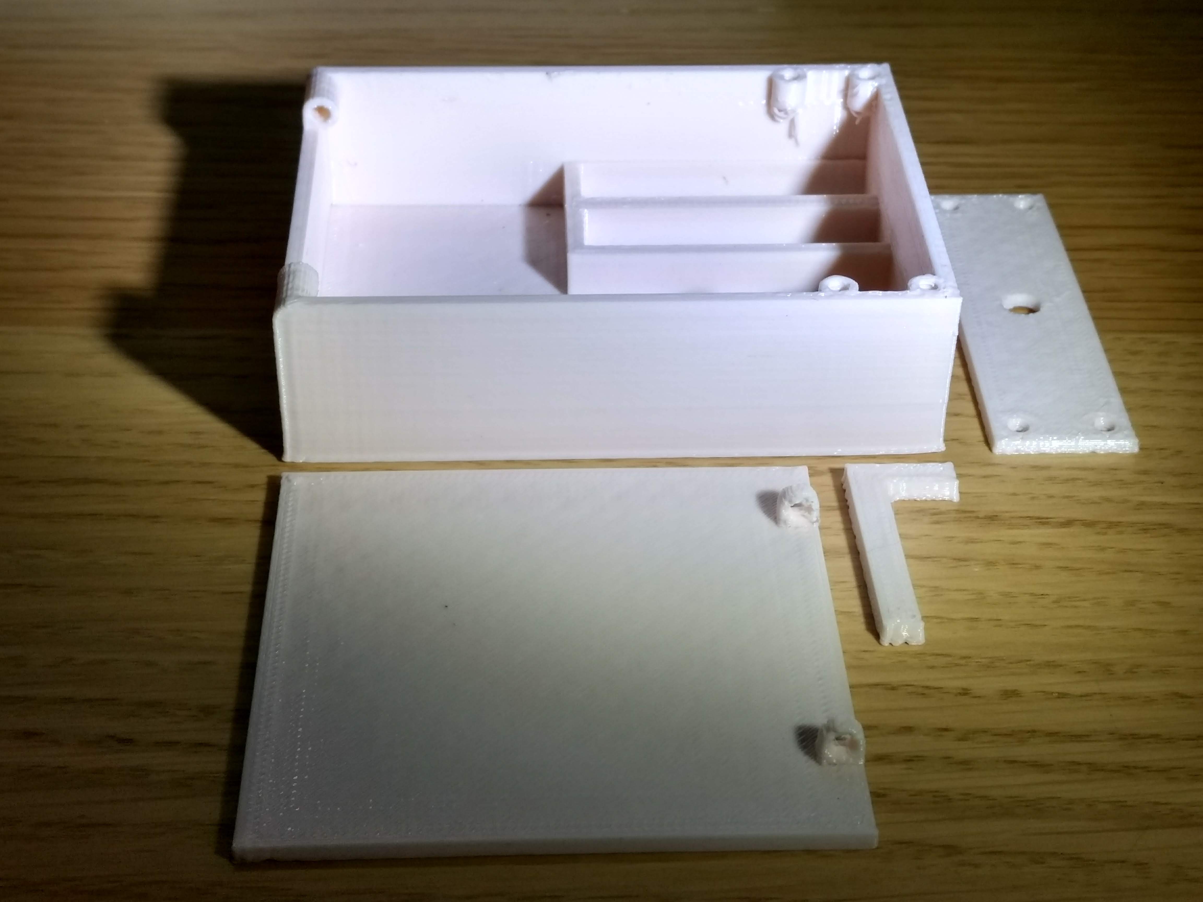
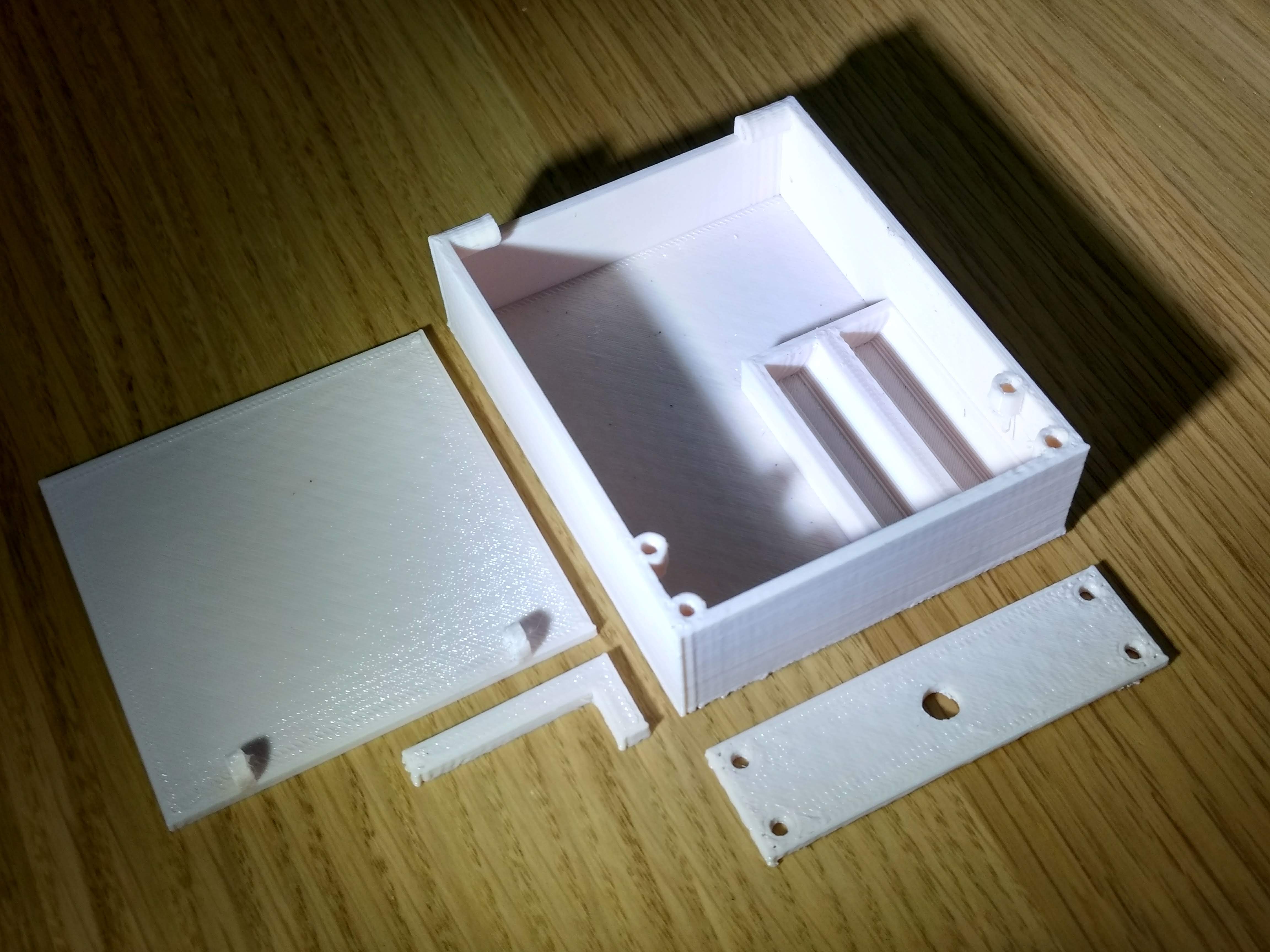
Here is some images of the printed model:
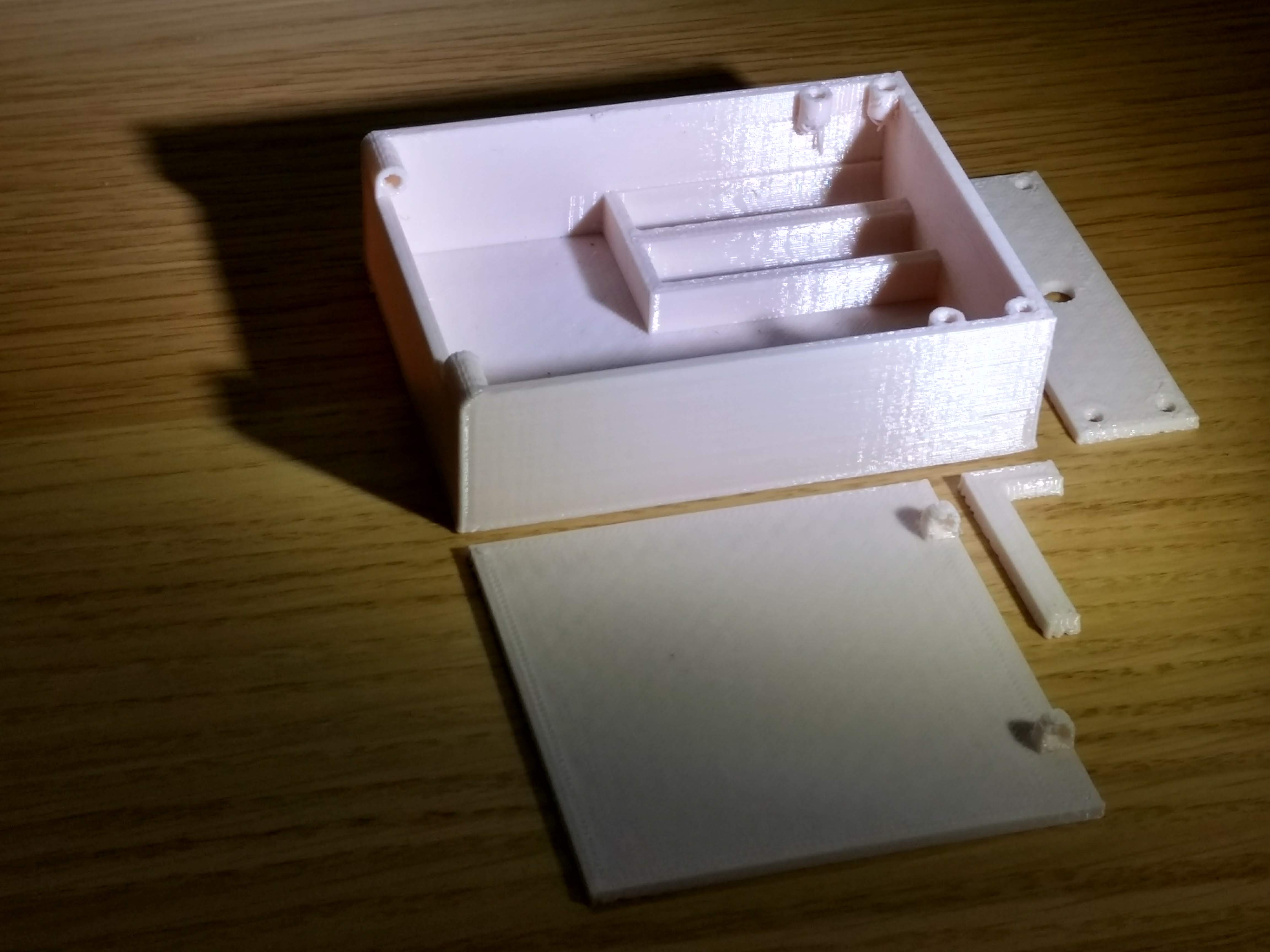
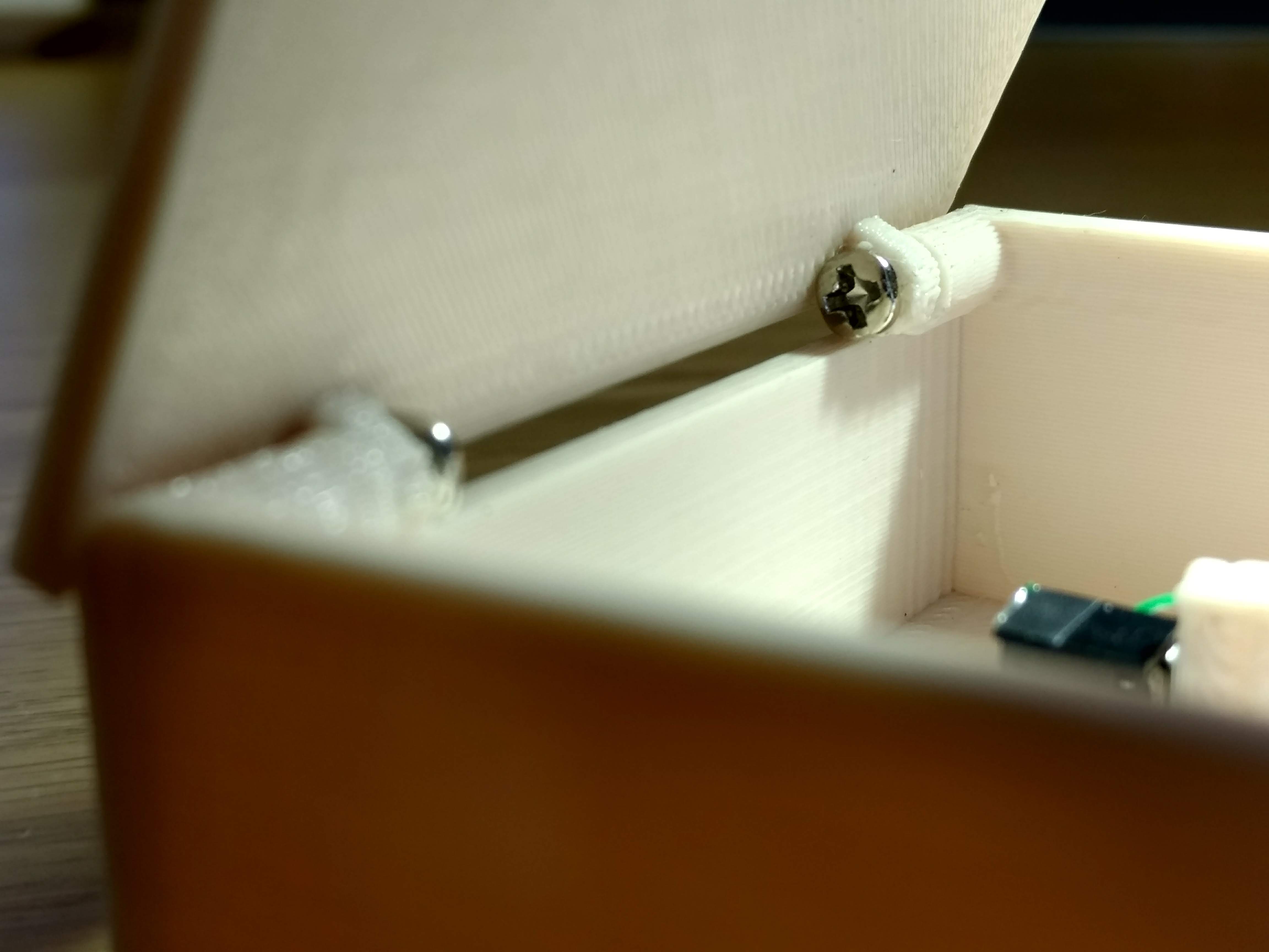
In particular, the part of the design that I am most proud of is the hinge. It has rounded corners on the back edge so that the lid can rotate around it, pivoting on the two 3mm screws that act as the hinge. Here it is:
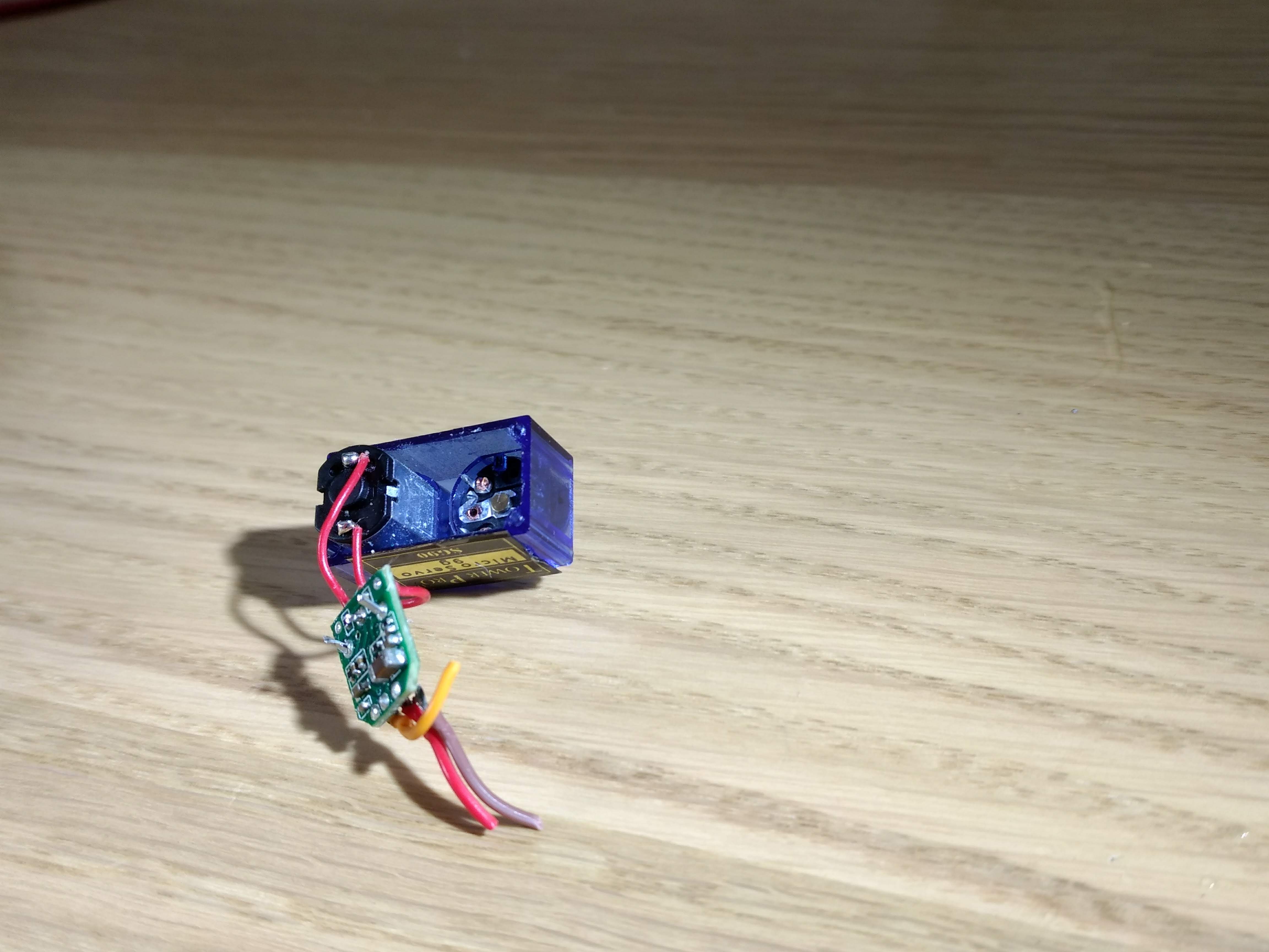
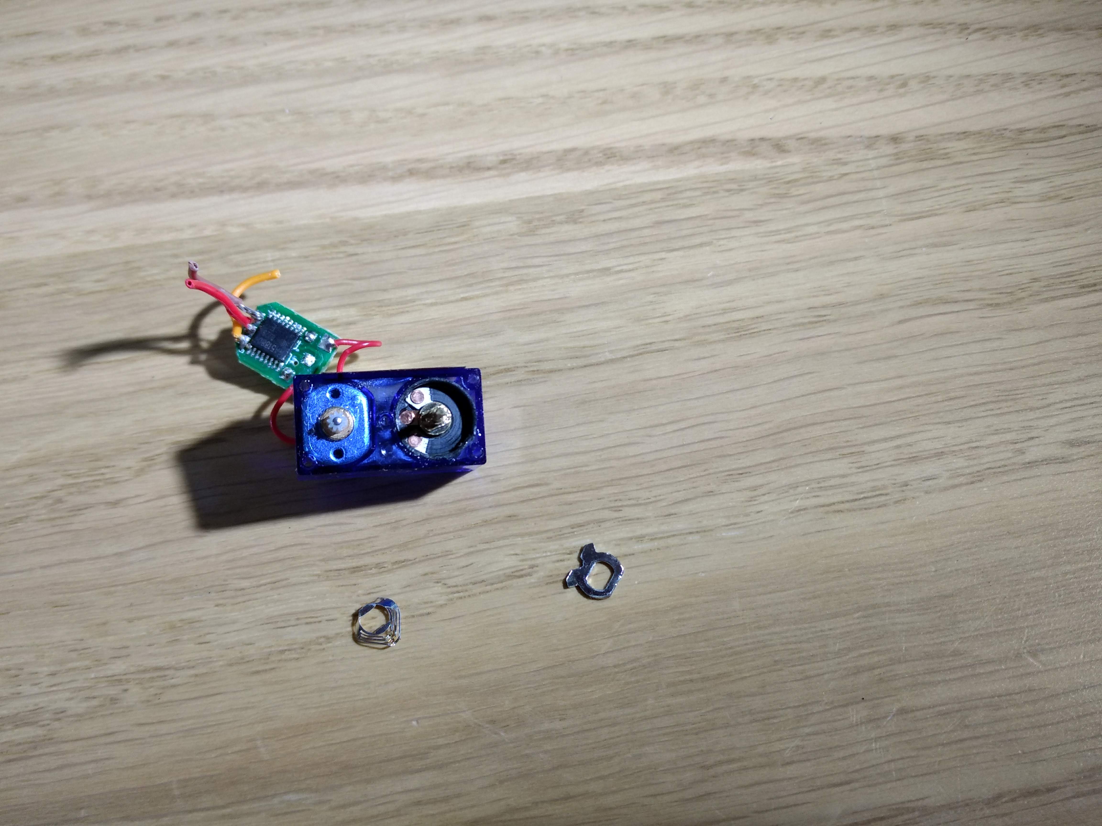
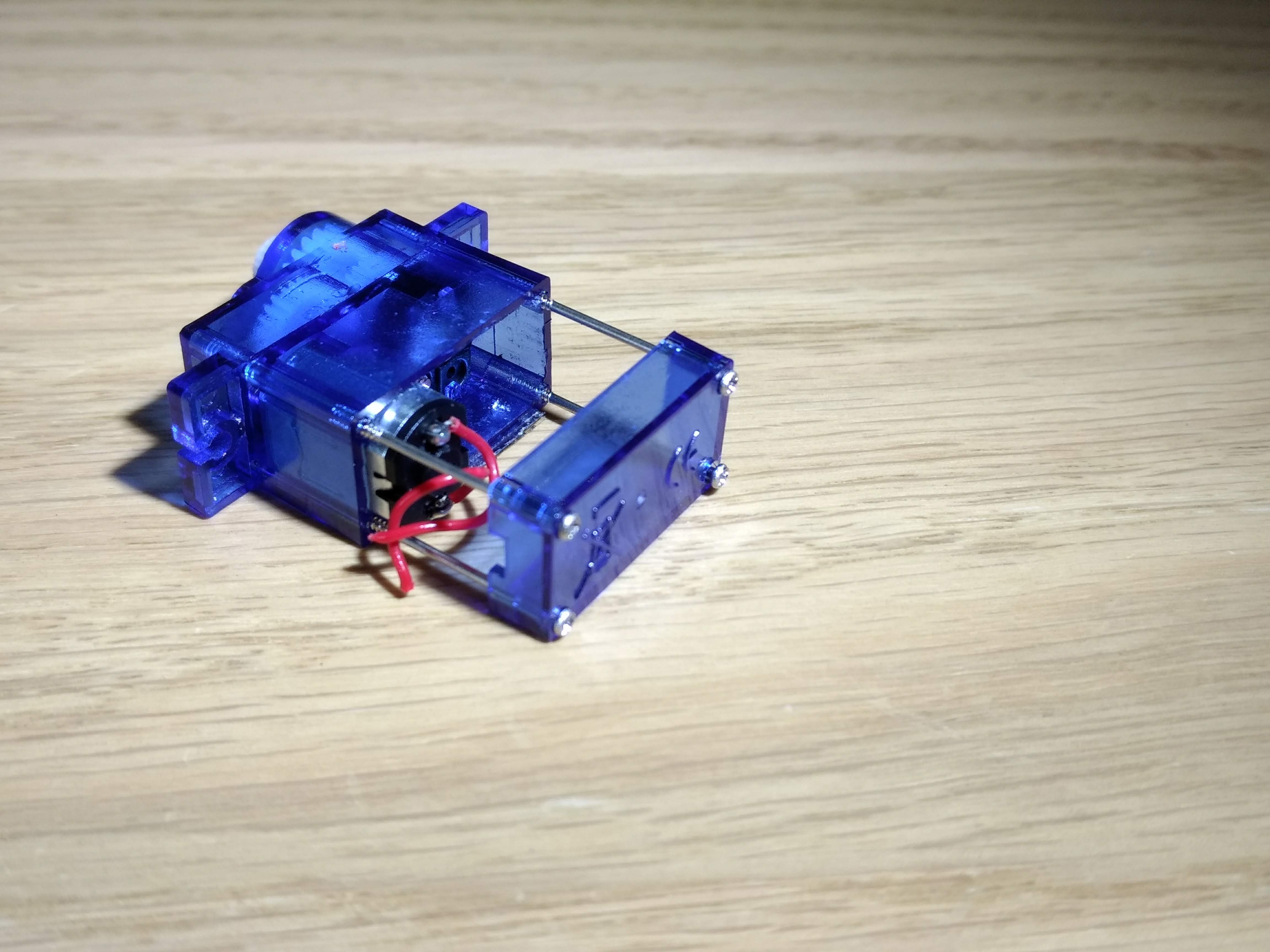
As for the electronics, I needed to remove the circuit board from an old servo so that I could use it as just a regular DC Motor (but with the much-needed gearing that the servo provides). In addition, the potentiometer (which is the input to the circuit board's control mechanism and acts as an axel for the cogs in the gearbox) only rotates 180 degrees. However, with some slight modification (ripping of a metal bracket on the front), I got the potentometer to free-spin so even though it remained locked to the outer cog, the outer cog could still turn indefinitely. Finally, two of the teeth from one of the cogs in this broken servo that I disassembled has been broken off so I stole the equivalent cog from a different servo that had failed for a different reason.
Here are some images of that process (the removal of the circuit board, the removed metal bit from the potentiometer and the destruction of what ended up being three failed servos):
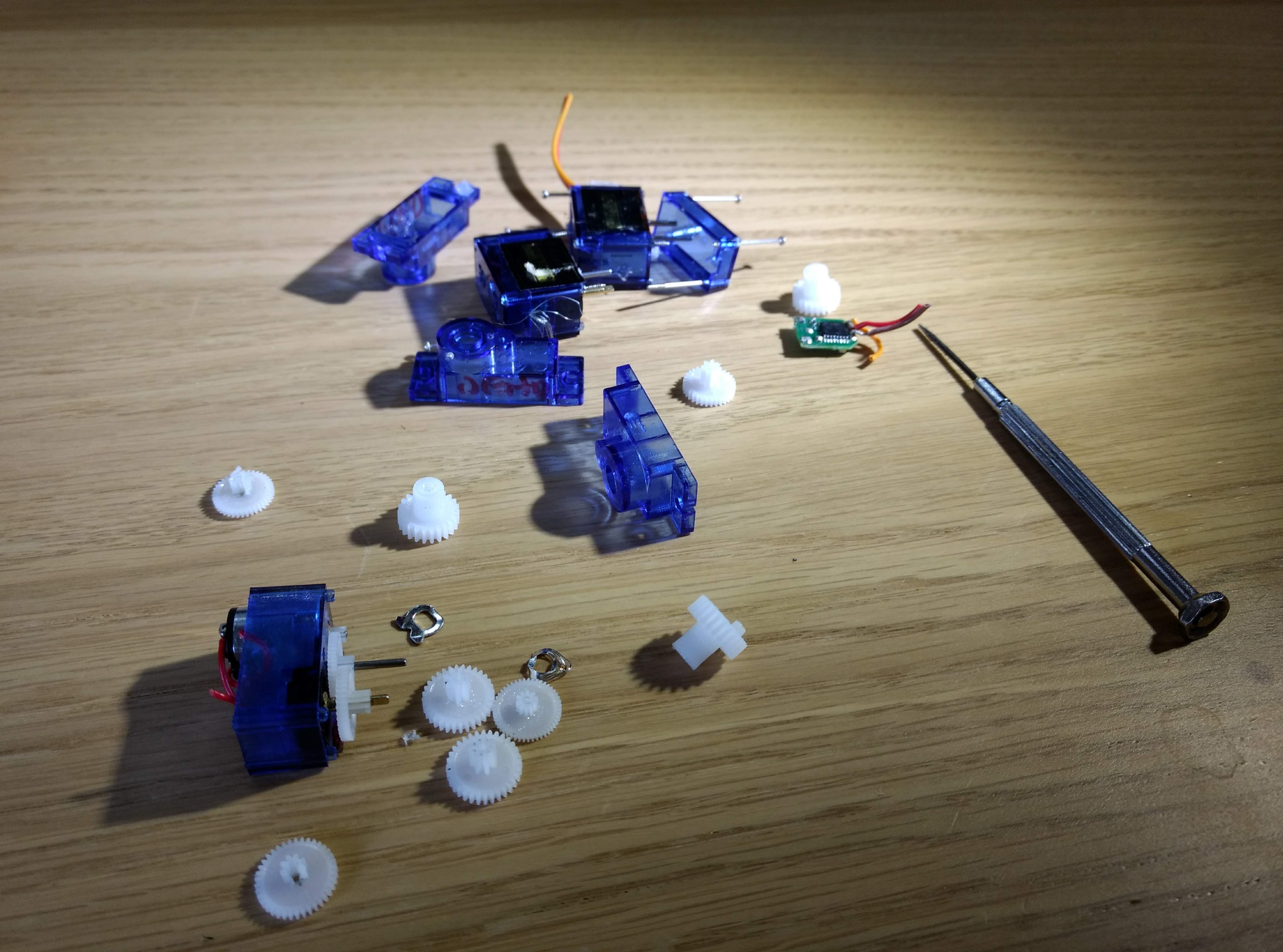
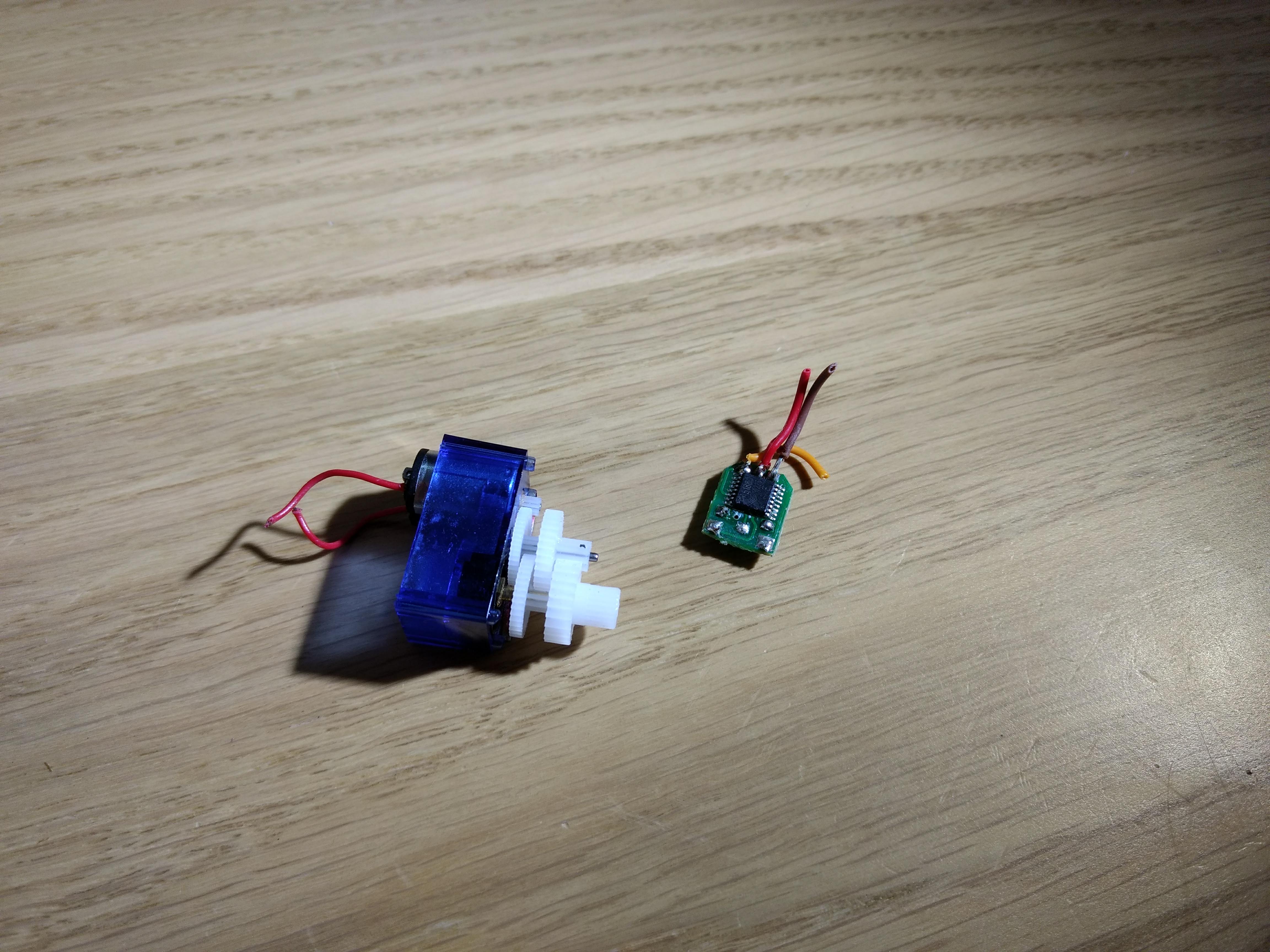
And here are two more images of the gear mechanism and it being screwed back together again:
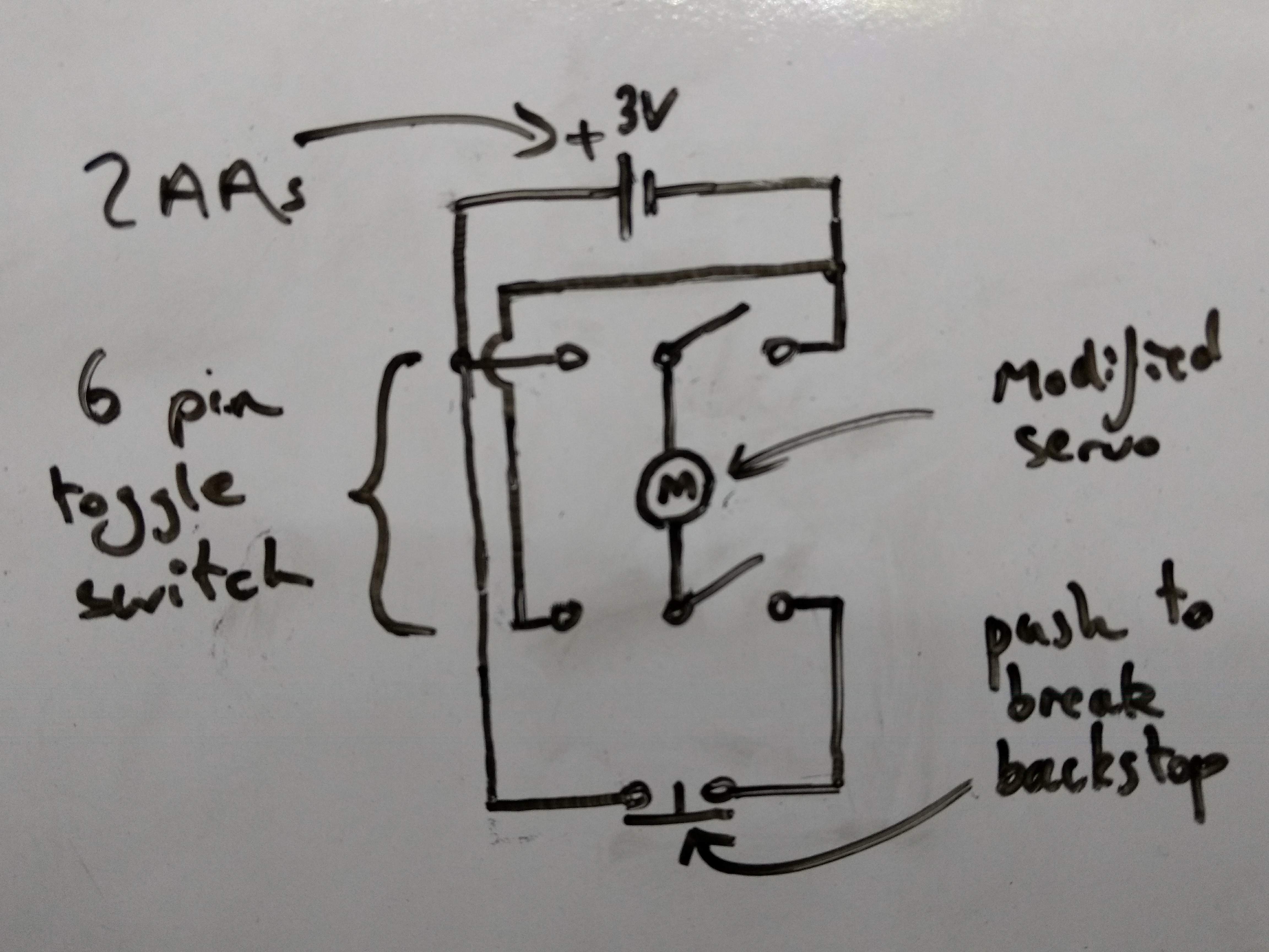
Then for the rest of the electronics, it was simply a matter of wiring the push to break endstop up to the 6 pin toggle switch in such a way that the motor always turned towards the switch whilst the switch was flipped one way and then only turned back towards the endstop whilst the endstop was not pressed.
Here is a rather unneat diagram of that setup:
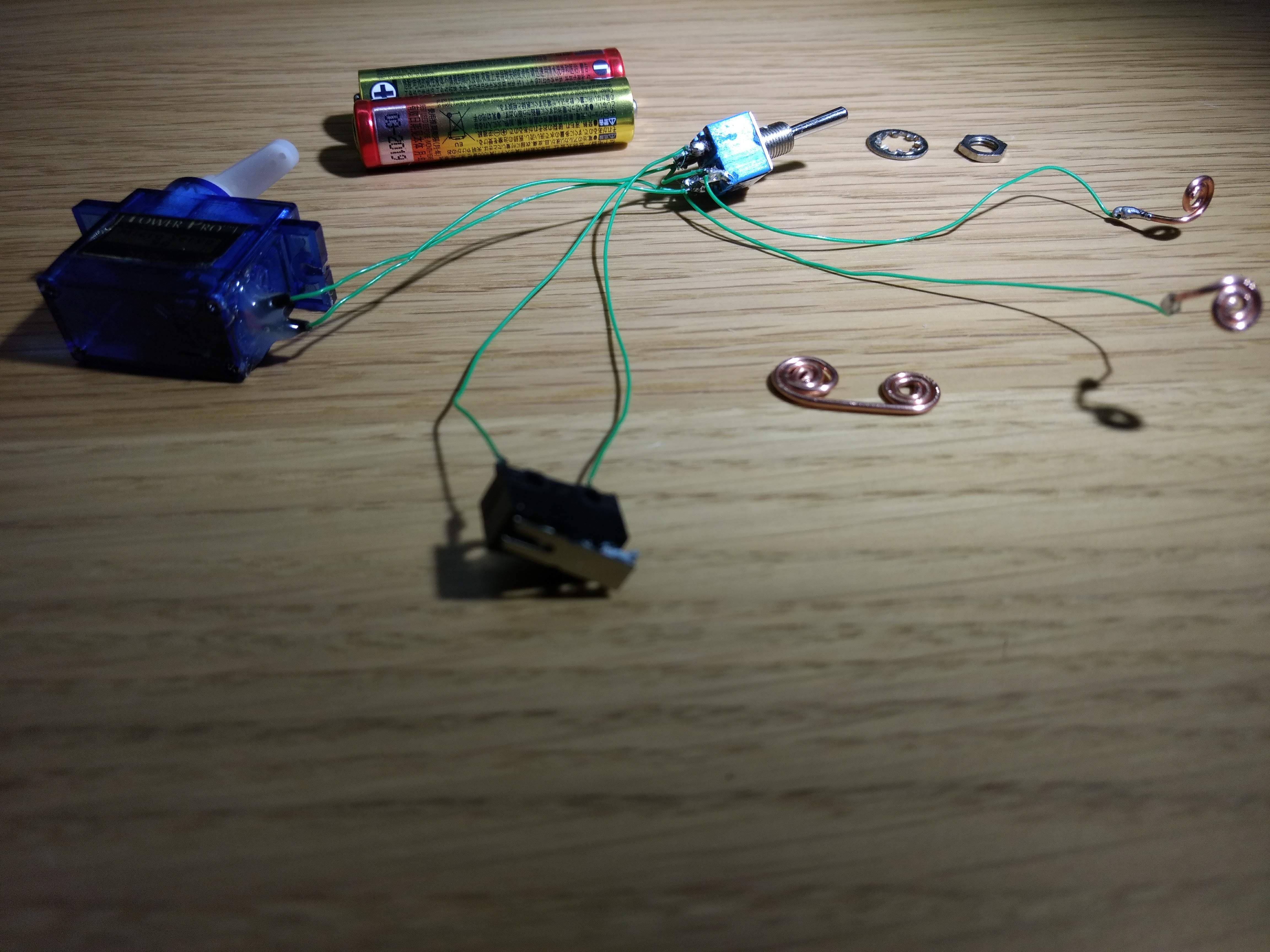
And here are the electronics all soldered together (I used coiled copper wire for the battery terminals):
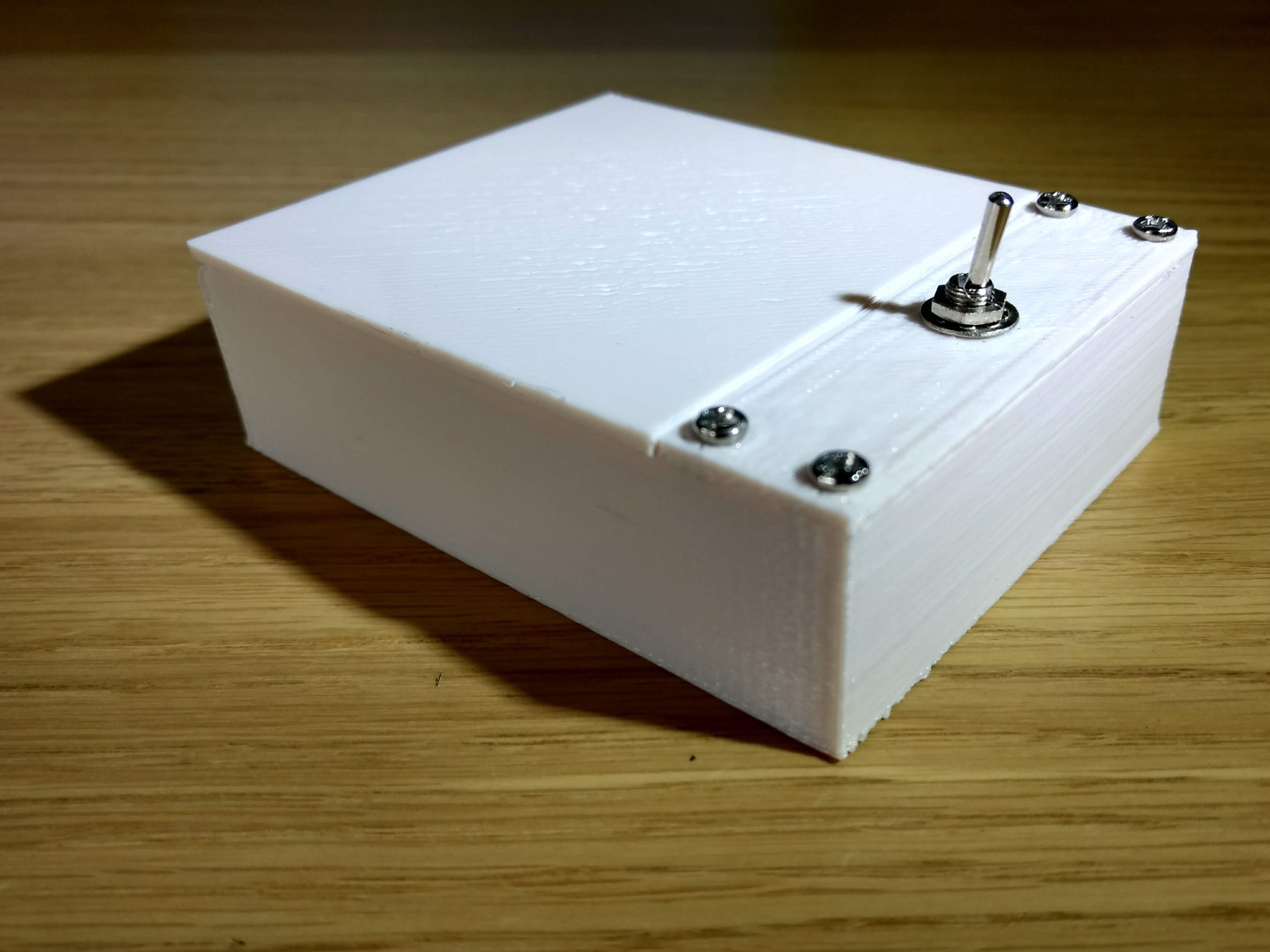
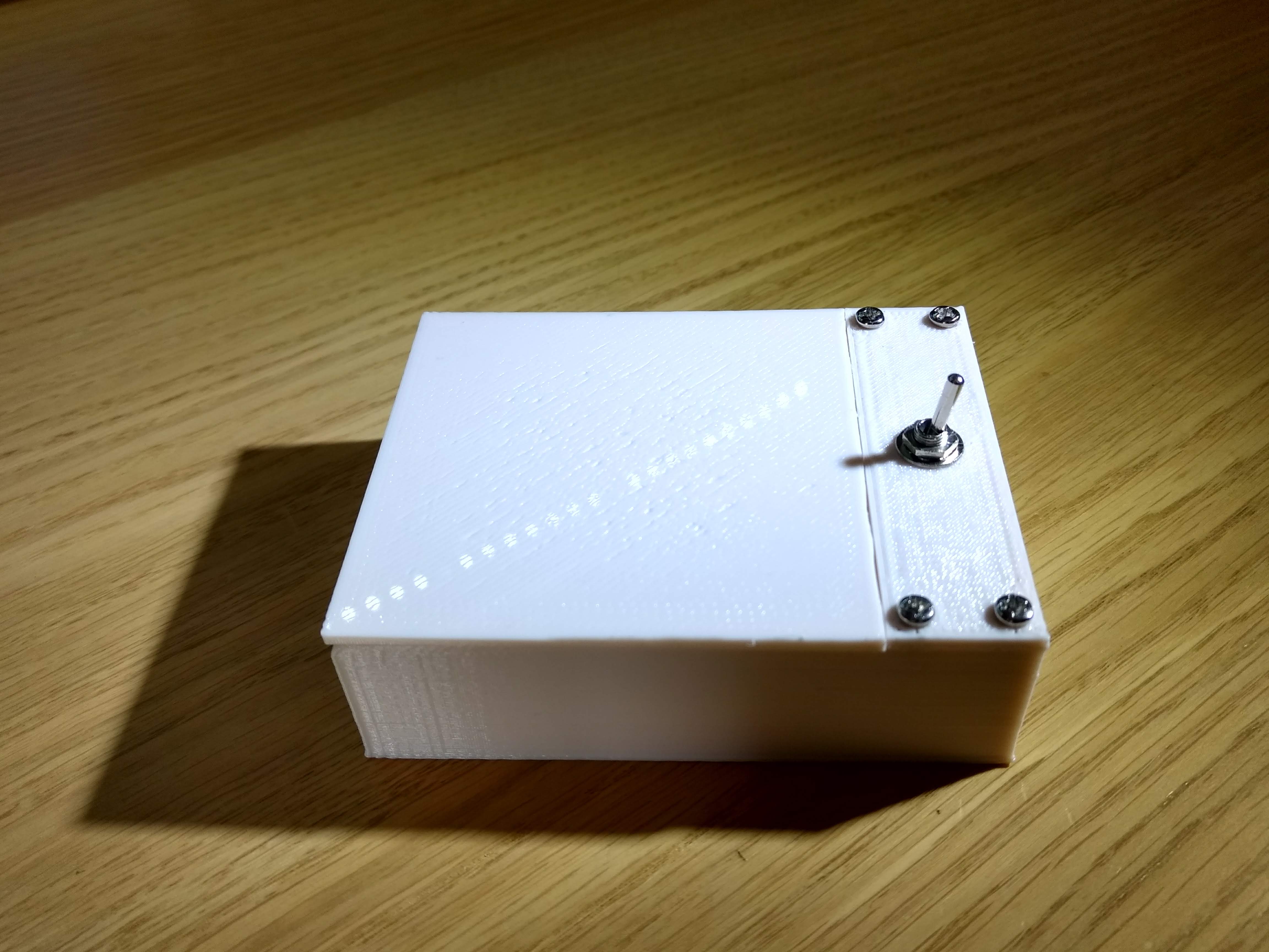
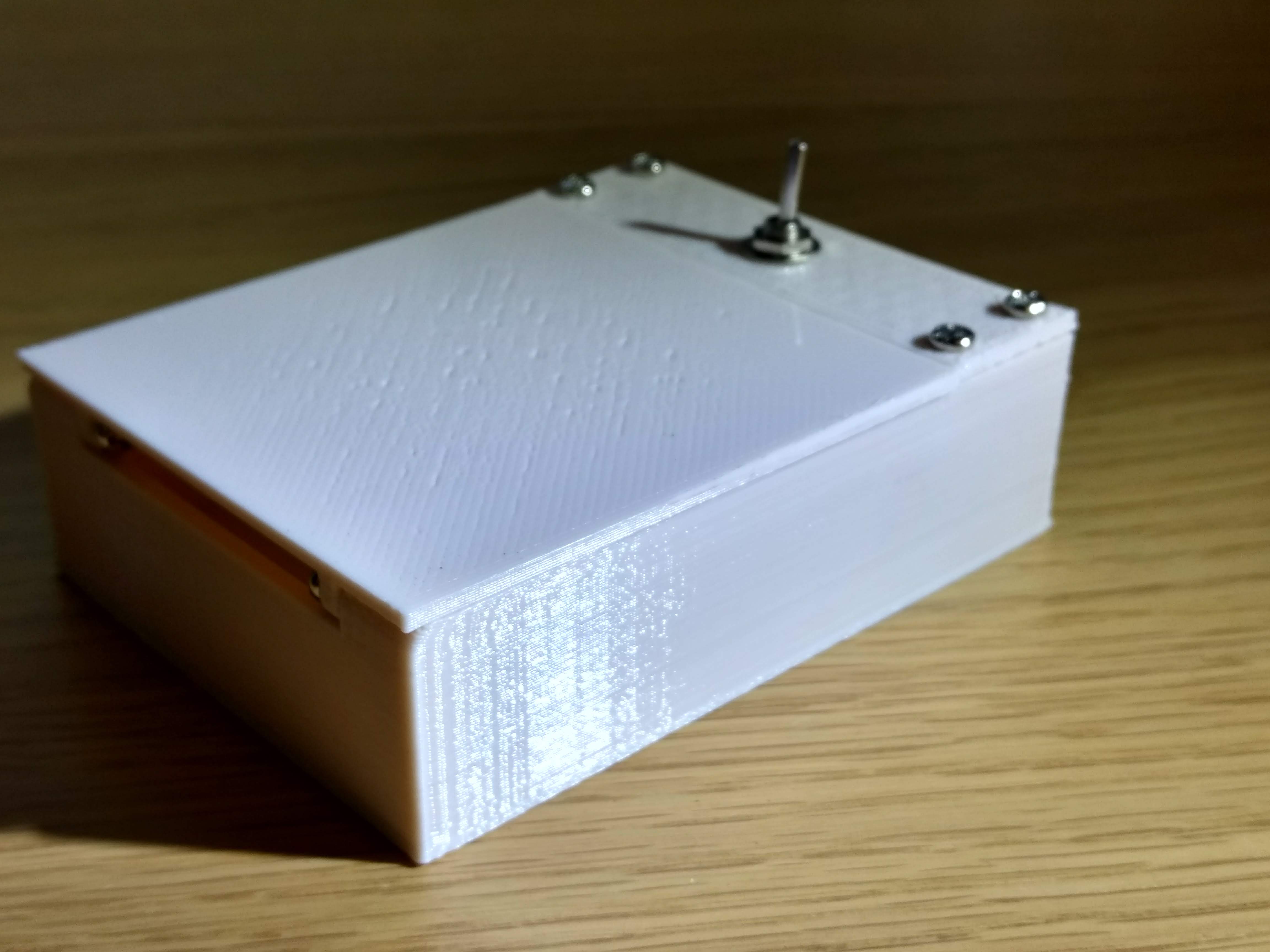
And that was about it. Here are some final images of the finished box: